UPDATE!! UPDATE !!
New released MPDMv4 (MAINS Power Dimmer) Driver Board !
————————————————————————————————————————–
WARNING!! You will play with LIVE MAINS!! Deadly zone!!
If you don’t have any experience and are not qualified for working with MAINS power I will not ecourage you to play arround!
—————————————————————————————————————————-
Remember the story about the WIFI MAINS Power Switch module?
Because of the high interest in the subject, a new dedicated Dev Board has been born: MPSMv2, a small ESP8266 DevBoard with integrated MAINS Power Switch!
Yes, it’s finally here, arrived safely from the PCB factory and you can see it below. I know a lot of you are waiting it already, but please be patient few more days. None of the already requested ones will leave the premises without a proper 24 hour test.
For any new requests please feel free to use as usual: tech at esp8266-projects.com.
If you want for your own experiments to order CBD v2 EVO bare PCBs only, you can also do it directly at Dirty PCBs, our preferred PCB House:
http://dirtypcbs.com/view.php?share=5615accesskey=401e206b2272f21313417ca77c1616d4
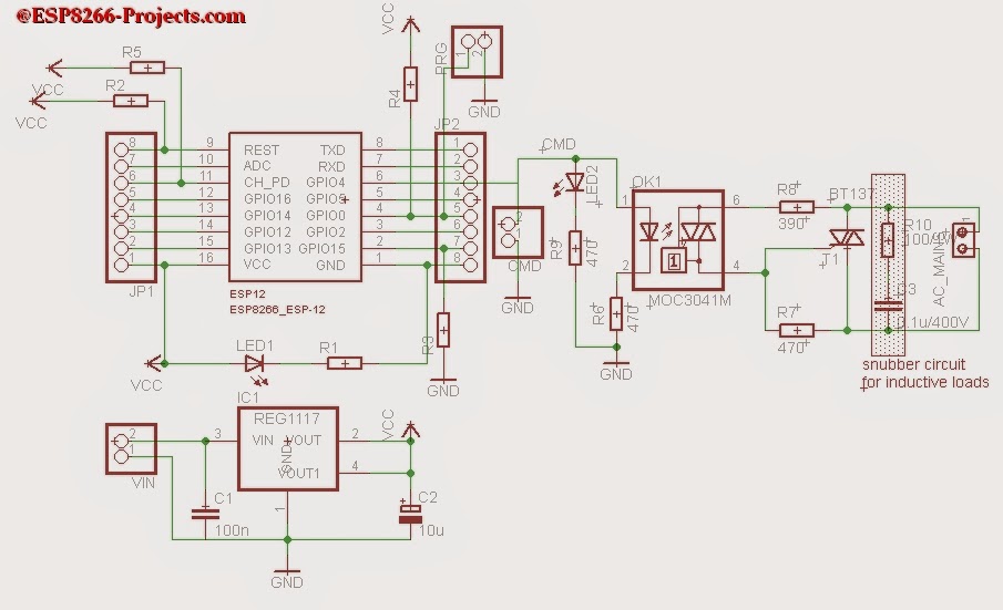 |
MPSM v2 Schematic |
Theory of operation remain the same so please take a look at the previous Article about MAINS Power Switch for deeper explanations.
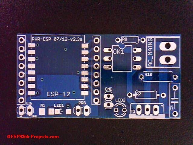
I don’t know if this it’s the smallest MAINS Power Switch with integrated WIFI and direct Web interface access but if is not, it’s definitely closer to be at only around 25x50mm 🙂
|
|
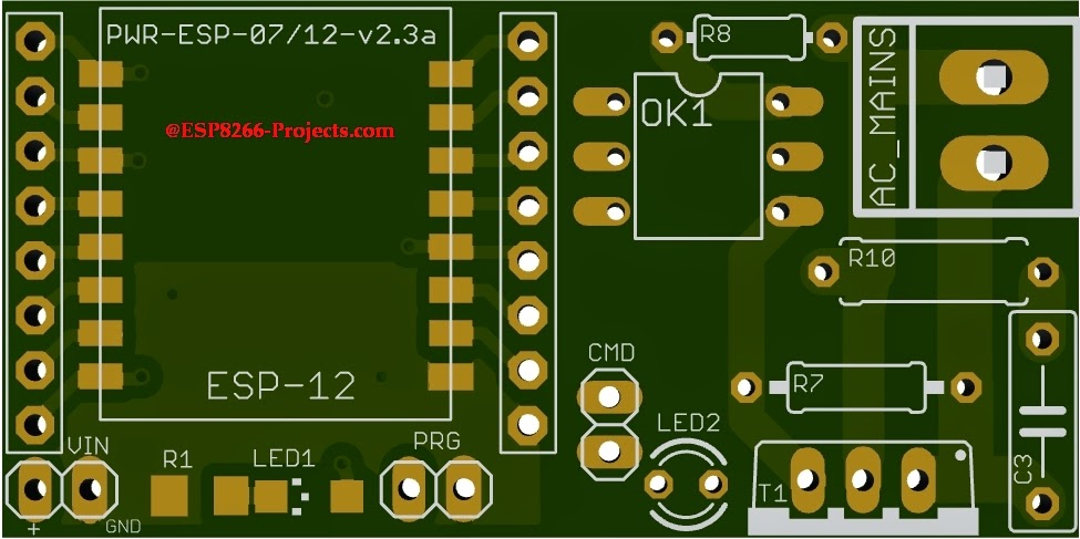
MPSM v2 – PCB – TOP |
As you can see from the PCB picture above you have even a full ESP8266 pinout access thru 2 breadboard friendly expansion slots for future projects development.
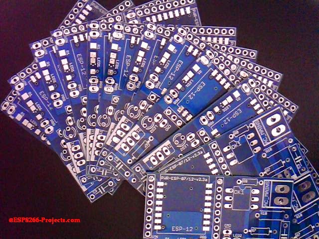
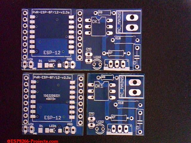
Finally, the received result from the PCB Factory, a long awaited moment:
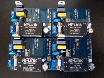
|
|
MPSM v2 PCB Batch |
|
|
MPSM v2 – TOP |
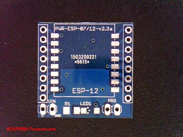
If you want to have a separate Breadboard friendly ESP8266 adapter with integrated 3.3V Power Supply, you can cut the board in 2 independent working parts, the ESP07/12 adapter and the MAINS Triac Switch.
It is designed in such way that no harm will be done by the cut to the functioning of the circuit. You can use the cut MAINS Power Switch part directly even with your ARM, PIC, Arduino, whatever MCU you like this days without any problems as long as it has a GPIO pin capable to drive the MOC Optocoupler LED.
|
|
MPSM v2 – separate usage ESP8266 adapter and MAINS Switch |
|
|
ESP8266 ESP-07/12 Adapter |
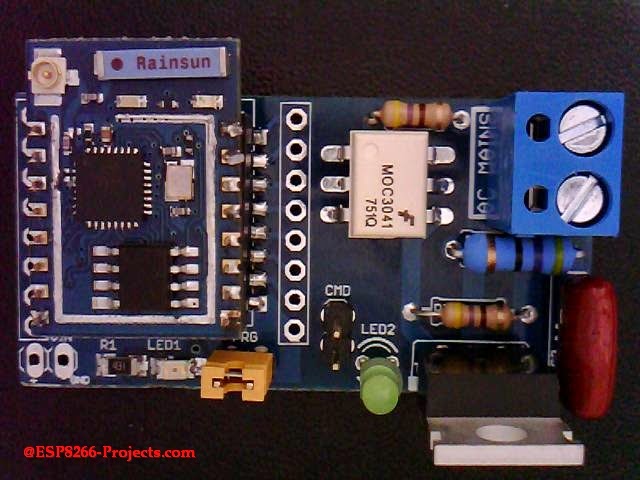
And the final result, a fresh baked one, ready for testing:
|
|
MPSM v2 – full asembled |
|
|
MPSM v2 – full asembled – bottom |
—————————————————————————————————————–
Before going further and start running some tests few considerations to be done:
- Do NOT use it without proper Knowledge about MAINS circuits !
- Do NOT use it without a proper FUSE on MAINS line!
- This is NOT a Toy!
—————————————————————————————————————–
What we will need:
- MPSM DevBoard from above
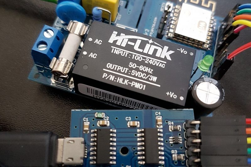
- USB adapter (take a look on Part 1 for details how to connect them together)
- NodeMCU firmware (download latest – can use the floating point version for now)
- NodeMCU Flasher ( firmware programmer for NodeMCU DEVKIT)
- For programming MPSM v2 DevBoard and uploading the software we will continue to use the LuaUploader as before.
Flashing the MPSM NodeMCU Firmware is a straigth away process:
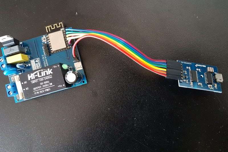
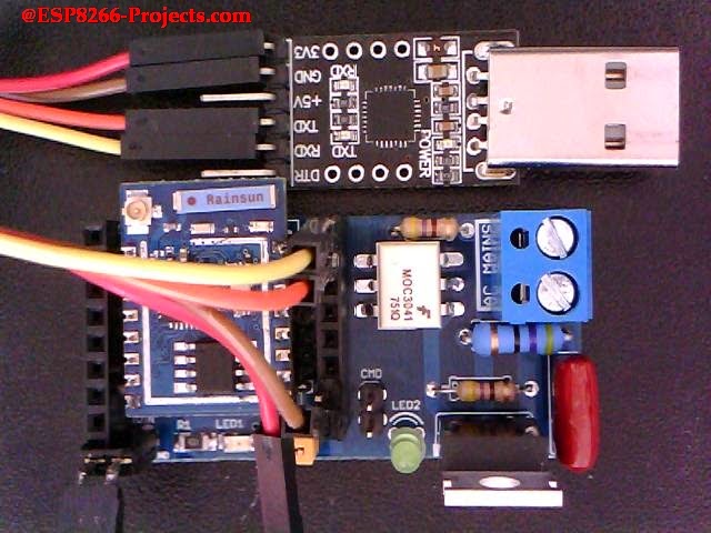 |
Programming MPSM v2 Board |
- Connect MPSM Board with the USB Adapter, Set the PROG jumper (YELLOW) in the Programming mode position (closed) and power on
- Start NodeMCU Flasher. Choose you USB adapter corresponding port
- Add from Config Menu latest previously downloaded firmware. It must start from 0x0000. Disable anything else.
- Go back on Operation tab. Power off your MPSM Board. Press FLASH Button. power ON quick MPSM Board. It will be recognised and will start flashing. Give it a second try if necessary.
- When finished succesfully A green OK checkmark will appear
- Power Off MPSM Board, Remove yellow jumper. Power back ON. A NodeMCU programmed MPSM Board is ready for action 🙂
For a more detailed explanation for NodeMCU Firmware flashing please take a look at CBDB Board Firmware Flashing discussion
To quick run a test we will use the code snippets provided by LuaUploader at start-up. Select the piece of code that you want to run and press “Execute Selection” button.
- To quick setup your WIFI network – If this is your first project with a new ESP module that was never used in your WIFI Network, don’t forget it – one time only :
-- One time ESP Setup --
            wifi.setmode(wifi.STATION)
            wifi.sta.config ( "YOUR_WIFI_SSID" , "PASSWORD" )
            print(wifi.sta.getip())
- For the Triac Optocoupler Command testing we will use the “Blinky” part of the code and if all ok it will blink LED2 with the choosen rate “dly”.
Run the modified code from below:
          -- Blink using timer alarm --
          timerId = 0 -- we have seven timers! 0..6
          dly = 500 -- milliseconds
          ledPin = 1 -- 1=GPIO5  - allocated pin for Triac opto command
          gpio.mode(ledPin,gpio.OUTPUT)
          ledState = 0
          tmr.alarm( timerId, dly, 1, function()
                ledState = 1 - ledState;
                 gpio.write(ledPin, ledState)
          end)
Now you can connect you MAINS powered lightbulb and you can see it playing the “Blinky” game too :). Use proper heatsink for power disipation for your Triac.
Power Switch function and WEB Server software are the same as in previous article about CBDB WIFI MAINS power switch just change the used GPIO Triac opto command pin from outpin=3 to outpin=1 to properly reflect our new MPSM v2 Board setup
For a MAINS Power Dimmer Module, take a look at the new MPDMv3 Module
1 Comment
Roman · October 5, 2018 at 10:04 am
The circuit is quite small, yes. But what I do not understand; from where gets the circuit its (5V-) Power (VCC)?
Or did I oversee the power supply on the PCB?
Regards
Roman