UPDATE!! UPDATE !!
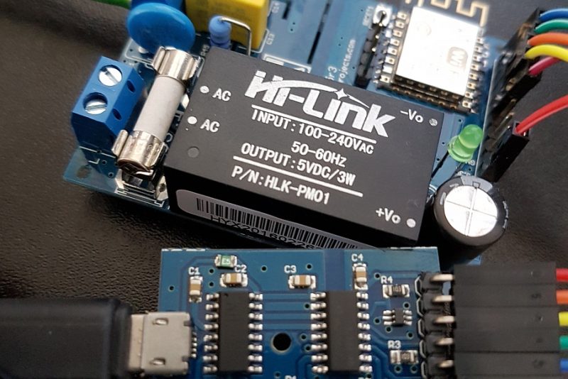
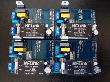
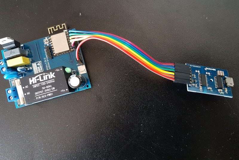
New released MPDMv4 (MAINS Power Dimmer) Driver Board !
If you don’t have any experience and are not qualified for working with MAINS power I will not ecourage you to play arround!
—————————————————————————————————————————-
For any new requests please feel free to use as usual: tech at esp8266-projects.com.
If you want to order MAINS POwer Dimmer/Switch bare PCBs only, you can also do it directly at Dirty PCBs, our preferred PCB House:
Now it’s about time to talk also about what many of you has asked for: DIMMING!
It’s a total different story, liitle bit complicated but, as you will see, not so hard to understand.
General considerations:
There are several types of dimmers generally available. These are used for resistive, and inductive loads, such as incandescent,cold cathode and low voltage (inductive) lamp sources. Note that not all electronic transformers used for low voltage lamps are suitable for dimming by Triac or Thyristors dimmers. In case of Thyristors you need 2 of them as Thyristor is a Unidirectional device and because AC power flows in both directions!
Why using Thyristors? One of the reasons is that they are available in higher power ratings than Triacs and are more robust. A 4-500 A to 1kA ratings is something common for Thyristors.
Usually you will find this kind of Thyristors in Industrial applications, not exacty a hobbist part.
Just look, for example, at the specifications of ABB 5STP27H2801 and you will understand why 🙂
I don’t remember a highly available Triac rated more than 40A. BTA40-700B is a good example.
For resistive loads ON-OFF only jobs (no dimming required) a winning combination is between MOC304X for Triac driver (Zero voltage crossing one) and a good quality Triac, decently sized at the power needs.
In case of dimming you DON’T want to use a zero crossing voltage one! And this is because of the way the dimming process is going and depending on our own ZCD (zero cross detection) function. In our case zero cross detection is done by the biphase optocoupler as in the schematic below
|
|
Mains power is comprised of an alternating current that flows in one direction and then in the other, along the cable, at the rate of 50 or 60 cycles per second.
The number of cycles in one second is called the frequency. The frequency is given in a unit called hertz (symbol Hz) where 1 Hz = 1 cycle per second .
The value 50 or 60Hz is dependent on the countries power system. The current alternates back and forth changing direction at the zero point.
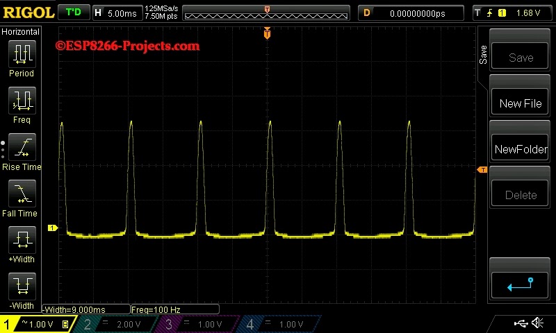
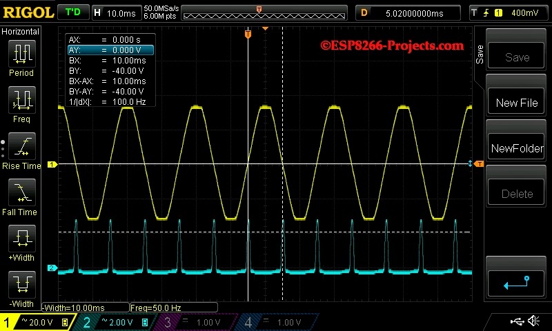
If we will to look at the waveform (yellow) with the Osciloscope it would appear as a sinusoidal shape. Drawing a line through the middle and this is what is called the zero crossing point. At this instant in time no current is flowing in either direction.
 |
|
| MAINS 50Hz and ZCD waveforms |
The Triac is electronically synchronized with the help of the ZCD to turn the power ON or OFF. By chopping the waveform at the zero-crossing point, smooth dimming can be achieved without the lamp flickering. This turning on and off of the power device occurs every time the mains crossing point is reached (half phase), 100 or 120 times per second (50 or 60Hz).
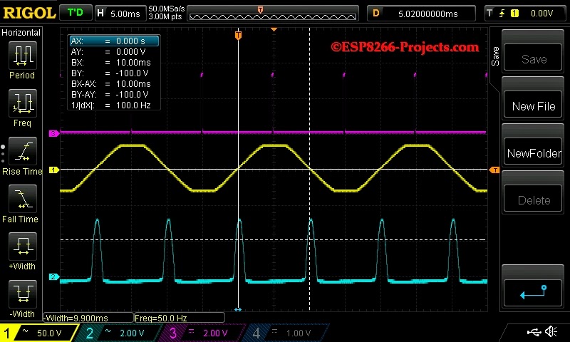 |
| Firing Triac at 50% |
ZCD determines the point in time (Firing delay time) at which they turn ON (conduct). The ON state continues until the next zero-crossing point, at which point the Triac turns itself OFF. The command circuit then provides a delay, which equates to the dimness of the lamp, before turning the control device back on. The slight capacitance of the load, filters the chopped waveform resulting in a smooth light output.
NOTE: If you notice that the 50Hz AC Voltage repesented up (yellow) is not around 240VAC and is nor pure sinusoide as should be, it’s a simple explanation: I didn’t want to put Osciloscope directly on MAINS. For very simple reasons. But this is not affecting at all the general view of the process.
What we will need:
- CBDB Board or any other ESP/Arduino /MSP/ARM/Whaterver Board you may like
- USB adapter (take a look on Part 1 for details about the USB Adapter)
- Main Power Dimmer/Switch module (MPDMv3 – details below)
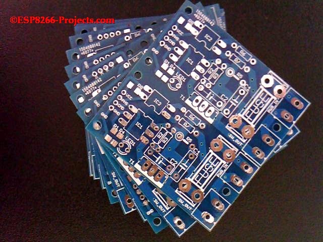
This time the MAINS Dimmer switch module was designed as a standalone unit, not including the ESP8266 anymore, as people were asking for a more general usage one that can be used with existing Setup/Environments.
Because the MPSMv2 was designed more as a DevBoard for MAINS switching application and the FUSE and MAINS input / output /filtering unit was keept separatelly has created some confusion and a lot of talks about, Hackaday thread included :).
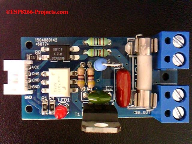
So, this time, you have on the same board, fuse and connectors to directly connect de MPDMv3 module to MAINS, Lightbulb/Lamp and your MCU Board.
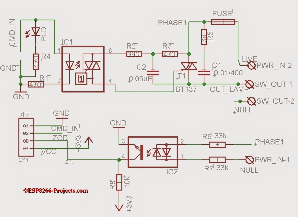 |
| MPDMv3 – Schematic |
 |
| MPDMv3 – MAINS Dimmer/Switch Module |
Both signals, phase detect (PHS) for ZCD and Triac command (CMD) are fully optocoupled and you have a proper galvanic separation between the low side and the MAINS side voltage, but, as a general practice DO NOT TOUCH any part of the circuit as long as MAINS power it’s applied!! The scope of LED1 is just to help you in the testing phase process, it does not have any other sense on dimming.
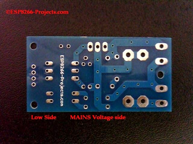
Proper clearance and creepage distance were also taken in consideration when PCB was designed:
 |
| MPDMv3 – PCB – Bottom side |
MPDMv3 Software
For programming CBDBv2 Board and uploading the driver and the software we will continue to use the LuaUploader as before.
1. Define used GPIO pin:
       outpin=7                                                       -- Select Triac Command pin - GPIO13
      gpio.mode(outpin,gpio.OUTPUT)
      gpio.write(outpin,gpio.LOW)                       -- Triac OFF
      inpin=6                                                         -- Zero crossing detector input - GPIO12
      gpio.mode(inpin,gpio.INT,gpio.PULLUP)   -- attach interrupt to ZCD
2. Zero Cross Detector function
As you have seen above on the Osciloscope, zero crossing is the moment when the sinusoide goes through zero. After each zero crossing there is one full half of the sinuswave available to send through the Triac to the Load.
So what the software needs to do is to detect the zerocrossing, and then wait for a set amount of time on that sinuswave to switch on the TRIAC.
We have a 50Hz VAC that means is 50 waves per second.
Each sinuswave thus takes 1000ms/50=20ms
They are 2 sinus peaks in a wave. That means that after every zero crossing detection there is a 10ms period that we can regulate.
If we switch Triac directly at the beginning of that period, the load will receive full power
If we do it at the end of that 10ms period the load will receive none and if we do it halfway, the load will receive half power.
Now, how can we obtain the desired number of dimming steps?
If you look at the above explanation you know already the answer: we will divide the 10ms to the number of the steps we want and that’s it. The obtained value can be tweaked a bit, depending on how is really looking your AC MAINS and how clean it is, filtering, delays, etc, but that’s the dimming steps value you need to start with.
Let’s assume we have:
Dimming steps = 128
Waveform Time= 10 ms
Step = 10000/128 = 78
Total dim time then is calculated as desired dimming steps * step value.
Also what we need to take in consideration after we fire the Triac is the Triac ON Propagation time (the time Triac needs to become fully ON).
       function zero_cross()
           dt = 76*dim
           --print("Zero cross detected!")
           stat = "ON"
           tmr.delay(dt)                                 -- Firing delay time calculated above
           gpio.write(outpin,gpio.HIGH)     -- Triac ON - Zero cross detected
           tmr.delay(100)                              -- Triac ON - Propagation time
          gpio.write(outpin,gpio.LOW)        -- Triac OFF - let's be sure it's OFF before next cycle 🙂
          tmr.wdclr()
          return stat
     end
3. Fading function for testing mode
      function fading()
         if(dim_up==1) then dim=dim+1
              else dim=dim-1
         end
         if(dim < 10) then dim_up=1 dim=10
              else if (dim > 120 ) then dim_up=0 dim=120
         end
         end
         print("Dimmer level : " .. dim)
         print("Fading mode  : " .. dim_up)
         tmr.wdclr()
    end
4. Main code
        dim = 120                                                          -- Dimmer level - smaller value is brighter
       dim_up=0                                                          -- Fading direction - for test  run
        gpio.trig(inpin,"up",zero_cross)                       -- ZCD interrupt attached - trigger on falling edge
       tmr.alarm(0, 100, 1, function() fading() end)     --timer for testing mode
For testing, just save the code on ESP as ‘dimmer.lua‘, restart ESP and run:
dofile("dimmer.lua") -- Start the Dimmer Testing mode
If you want the MPDMv3 software to start automatically when your CBDB module starts or reboots, then you neet to create and add some lines in your ‘init.lua‘ file:
dofile("dimmer.lua") -- Start the Dimmer Testing mode
Save the code on ESP as ‘init.lua‘, restart ESP. It should reboot and restart automatically the program.
As requested, please find below MPDMv3 BOM:
| No | Part | Value | Package | Description |
| 1 | R1 | 470 | R1206 | RESISTOR, European symbol |
| 2 | R2 | 360/1W | 0204/7 | RESISTOR, European symbol |
| 3 | R3 | 470/1W | 0204/7 | RESISTOR, European symbol |
| 4 | R4 | 470 | R1206 | RESISTOR, European symbol |
| 5 | R5 | 39/1W | 0207/5V | RESISTOR, European symbol |
| 6 | R6 | 47k/1W | 0207/10 | RESISTOR, European symbol |
| 7 | R7 | 47k/1W | 0207/10 | RESISTOR, European symbol |
| 8 | R8 | 10k | R1206 | RESISTOR, European symbol |
| 9 | C1 | 0.01uF/400 X2 | C075-032X103 | CAPACITOR, European symbol |
| 10 | C2 | 0.05uF/400V | C075-032X103 | CAPACITOR, European symbol |
| 11 | IC1 | MOC3021 | DIL06B | 6-Pin DIP Optoisolators Triac Driver Output |
| 12 | IC2 | SFH620A | DIL04 | Optocoupler, Phototransistor Output, AC Input |
| 13 | T1 | BT137 | TO220BV | TRIAC |
| 14 | PLD | CHIPLED_1206 | LED | |
| 15 | PWR_IN | DG3XX-02-5.0 | DG306-5.0-02P | DG350-3.5-02P |
| 16 | SW_OUT | DG3XX-02-5.0 | DG306-5.0-02P | DG350-3.5-02P |
| 17 | FUSE | 5A | SHK20Q | Fuse |
| 18 | U$3 | 1X4 | 1X4 | 2mm Header or 2mm socket |
That’s all for today, next time we will talk about WEB Interface implementation for our MAINS Power Dimmer / Switch Module!
