PCA9685 Extension Board Module Available also on Tindie!
ESP Basic Tutorials Series: PCA9685-16Channel 12-bit PWM I²C-bus LED controller Driver – Part 1
If you are looking for a very simple to use 16 Channel LED controller or just for a nice 16 Channel, high resolution PWM driver then this one is for you!
The PCA9685 is an I²C-bus controlled 16-channel LED controller optimized for Red/Green/Blue/Amber (RGBA) color backlighting applications.
What we will need:
- ESP8266 nEXT EVO Board ( Bare PCB available directly at DirtyPCB’s Shop )
- PCA9685 Extension Board Module like the one from here.
- For programming and uploading the driver and the software we will use the ESPBasic
Connection with the ESP8266 nEXT EVO Board is very easy, as PCA9685 Module connector is fully compatible with the nEXT Bus connector.
Driver implementation
As been a I2C compatible device you need to have a standard I2C Bus Initialisation function as usual and also to know the I2C address of the device.
For a more detailed hardware overview go to PCA9685 General Description Article.
Software:
1. Main program:
 i2c.setup(4,5) 'choose your I2C bus pins

dev_addr = 64  '0x40 - I2C Address for the PCA9685

mode1 = 0    '0x00 location for Mode1 register address
mode2 = 1    '0x01 location for Mode2 reigster address
led0 = 6     '0x06 location for start of LED0 registers
rst = 1      '0x01 reset device
rval = 0     'read register value

led_on = 4096
led_off = 0

ledN = 0

dim led_stat(8)
led_stat(0)=0
led_stat(1)=0
led_stat(2)=0
led_stat(3)=0
led_stat(4)=0
led_stat(5)=0
led_stat(6)=0
led_stat(7)=0


stat = "Init.."

'reset device     write_reg(mode1, rst)
reg = mode1
data = rst
gosub [WRITE_REG]

'check if proper initialised
gosub [READ_REG]
'wprint rval
if rval == "1" then
   status = true
   stat = "PCA9685 Init OK"
else
   status = false
   stat = "PCA9685 Init Failure!"
end if

wprint " <b>PCA9685 - 16Channel 12-bit PWM I2C bus LED controller<br>driver demo</b><br><i>by tech@esp8266-projects.com</i><br><br><br>"
wprint "Initialisation Status: "
textbox stat

'set for auto-increment
let data = 160
gosub [WRITE_REG]

'Choose below the desired output mode!
'Direct LED connection
'set to output mode INVRT = 1 OUTDRV = 0
reg = mode2
data = 16
gosub [WRITE_REG]


'External N-type driver
'write_reg(mode2, 0x04)   -- set to output mode INVRT = 0 OUTDRV = 1

'External P-type driver
'write_reg(mode2, 0x14) --set to output mode INVRT = 1 OUTDRV = 1

'choose LED_N - ON
wprint " <br>Input LED number : "
textbox ledN
wprint "<br> <br>"
button " Set LED ON ",[SetON]
button " Set LED OFF ",[SetOFF]
wprint "<br> <br> <br>"
button "LED 0",[LED0]
button "LED 1",[LED1]
button "LED 2",[LED2]
button "LED 3",[LED3]
button "LED 4",[LED4]
button "LED 5",[LED5]
button "LED 6",[LED6]
button "LED 7",[LED7]
wprint "<br> <br><br>"
button "LOOP",[loop]
wprint "<br> <br><br> <br>"
button "EXIT",[Exit]
wait
2. LOW Level subroutines
2.1 WRITE Register “reg”
[WRITE_REG]
i2c.begin(dev_addr)
i2c.write(reg)
i2c.write(data)
i2c.end()
return
2.2 READ Register “reg”
[READ_REG]
i2c.begin(dev_addr)
i2c.write(reg)
i2c.end()
i2c.begin(dev_addr)
i2c.requestfrom(dev_addr,1) 'start a transaction to read 1 byte
rval = i2c.read()           'read the byte
i2c.end()
return
2.3 WRITE LED_N Register
[WRITE_LED]
i2c.begin(dev_addr)
i2c.write(led0+4*ledN)
ah = led_on >> 8
al = led_on and 255
i2c.write(al)
i2c.write(ah)

ah = led_off >> 8
al = led_off and 255
i2c.write(al)
i2c.write(ah)
i2c.end()
return
3. BUTTON Subroutines
[LED0]
ledN = 0
gosub [LED_SW]
wait

[LED1]
ledN = 1
gosub [LED_SW]
wait

[LED2]
ledN = 2
gosub [LED_SW]
wait

[LED3]
ledN = 3
gosub [LED_SW]
wait

[LED4]
ledN = 4
gosub [LED_SW]
wait

[LED5]
ledN = 5
gosub [LED_SW]
wait

[LED6]
ledN = 6
gosub [LED_SW]
wait

[LED7]
ledN = 7
gosub [LED_SW]
wait
4. LED_N Switch subroutine
[LED_SW]
if led_stat(ledN) = 0 then
   led_stat(ledN) = 1
   led_on = 4096
   led_off = 0
   gosub [WRITE_LED]
else
   led_stat(ledN) = 0
   led_on = 0
   led_off = 4096
   gosub [WRITE_LED]
end if
return
5. ON / OFF Subroutines
[SetON]
led_on = 4096
led_off = 0
gosub [WRITE_LED]
wait


[SetOFF]
led_on = 0
led_off = 4096
gosub [WRITE_LED]
wait
6. FOR loop demo
[loop]
For x = 0 to 8
ledN = x
gosub [LED_SW]
Next x
For x = 8 to 0 step -1
ledN = x
gosub [LED_SW]
Next x
wait
7. EXIT Program subroutine
[Exit]
end
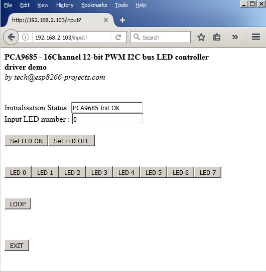
In the ESP Basic Web editor interface Type & Save your program as “PCA9685.bas” and Run it.
If all OK the result should look as below: