New goodies hit my MailBox, this time from Singapore :

Let’s see what’s inside.
- Short but nice documentation including, schematics, pinout, configuration:
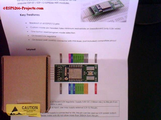
YES! It’s a new breadboard adapter for ESP-07 or ESP-12 ESP8266 WiFi module, designed by
Baoshi
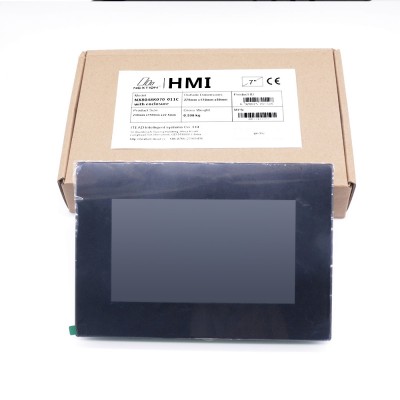
- a box containing the module nice packed in antistatic bag.


- Actual module zise vs. the printed A4 documentation
 |
|
| ESP Adapter Module Pinout |
A closer look:
 |
|
| TOP |
 |
|
| Bottom |
 |
| Onboard 3.3V power regulator – AMS1117 |
ESP Adapter board modules are about16mm tall, easily occupies 6 rows (3 rows on each side) on a Breadboard:

Features
- Easy breakout of all ESP07/12 pins
- Custom designed pin headers take minimum real-estate on breadboard
- Plug-n-play solution. No external pull-up / pull-down resistor necessary
- One button reset/program mode selection (short press for reset, long press to enter program mode)
- On-board 3.3v regulator with appropriate heatsink
- On-board UART (UART0) connector with FTDI Basic compatible pinout for easy programming and debugging
All the shematics and related informations are released under CC-0 Licence and can be found on GitHub: https://github.com/baoshi/ESP-Breakout
 |
|
| ESP Adapter Board Schematic |
One thing that definitely worth to mention is the clever way to combine RST and GPIO-0 pins signals to obtain the desired boot sequence modes during power on or reset with just one switch (SW1)
How it works:
During idle state, internal pull-up in the ESP8266 RESET pin turns on Q1. Q2 cut off so GPIO0 remains high due to GPIO0 internal pull-up. At the same time, C1 discharges from R2 and Q1. When user presses SW1, RESET goes low immediately. Meanwhile, Q1 turns off and 3.3V power charges C1 through R1 and R2. If user releases SW1 quickly and the voltage across C1 has not reached Q2′s threshold voltage, Q2 remains off and ESP8266 enters normal running mode. However if user holds SW1 long enough before releasing, Q2 will turn on, pull GPIO0 low. At the moment user releases SW1, RESET goes high but GPIO0 will be held low for a while due to C1 have to discharge through R2 and Q1. The choice of C1 and R2 are such that it keeps GPIO0 low long enough for ESP8266 to enter program mode.”
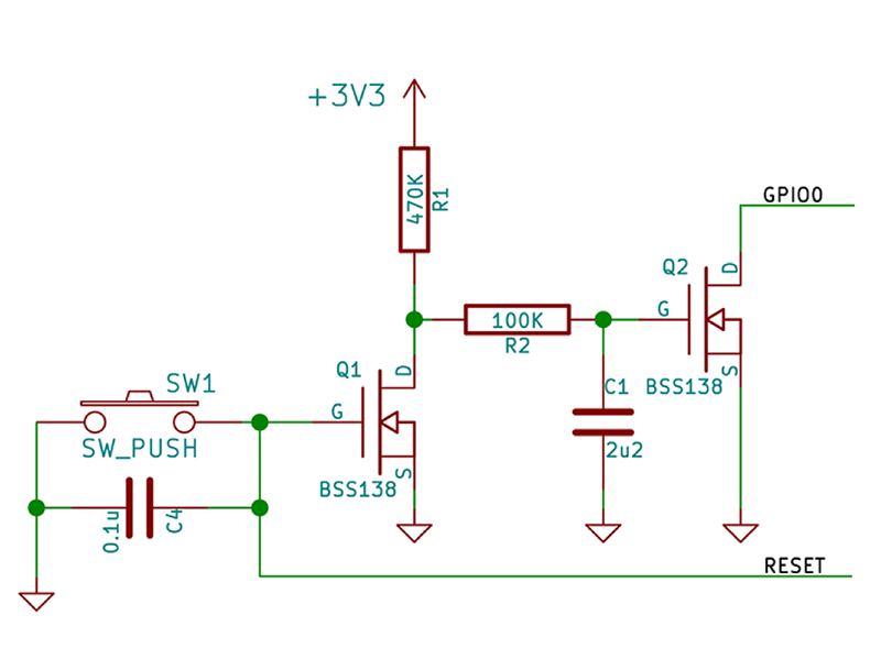 |
| SW1 Select circuit |
Different boot modes during power on or reset:
| Boot Mode | CH_PD | GPIO15 | GPIO0 |
| Run firmware | High | Low | HiZ (Internal P-UP) |
| Flash firmware | High | Low | Low |
Let’s run a first test on it !
Plug in the On-board UART (UART0) connector the USB adapter, 74880bps, 8N1, no handshake, choosing the right corresponding port. Be sure that is a 3V compatible one!! 5V logic levels might hurt badly your ESP8266 Module!
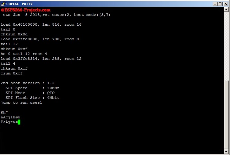 |
| ESP8266 Module Boot message |