At least from the zillions of request for a DAC Driver implementation example that I received in the latest weeks, this is the long awaited topic: ESP8266 Modules and Voltage Output Digital-to-Analog Converter control!
For our project we will use Microchip MCP4726, a Voltage Output Digital-to-Analog Converter (DAC) with EEPROM and I2C™ Interface.
As you will see, despite the fact that is a tiny one, it’s a very versatile chip with a great price/capabilities ratio. If you take a look on Digikey for example it can be found at around 1.15$!
Features:
• Output Voltage Resolutions:
– 12-bit: MCP4726
– 10-bit: MCP4716
– 8-bit: MCP4706
• Rail-to-Rail Output
• Fast Settling Time of 6 μs (typical)
• DAC Voltage Reference Options:
– VDD
– VREF Pin
The VREF pin or the device VDD can be selected as the DAC’s reference voltage. When VDD is selected, VDD is connected internally to the DAC reference circuit. When the VREF pin is used, the user can select the output buffer’s gain to 1 or 2. When the gain is 2, the VREF pin voltage should be limited to a maximum of VDD/2.
That means that it has also an internal reference and if you don’t need very high accuracy or you have a very stable power supply for MCP4726 DAC, you don’t need to use an external expensive Voltage Reference to make it working decent! If you are looking in the basement after boson Higgs cousin then this 1.15$ DAC is not what are you looking for 🙂
• Output Gain Options:
– Unity (1x)
– 2x, only when VREF pin is used as voltage source
• Nonvolatile Memory (EEPROM):
– Auto Recall of Saved DAC register setting
– Auto Recall of Saved Device Configuration (Voltage Reference, Gain, Power-Down)
• Power-Down modes:
– Disconnects output buffer
– Selection of VOUT pull-down resistors (640 kΩ, 125 kΩ, or 1 kΩ)
• Low-Power Consumption:
– Normal Operation: 210 μA typical
– Power-Down Operation: 60 nA typical (PD1:PD0 = 11)
• Single-Supply Operation: 2.7V to 5.5V
• I2C™ Interface:
– Eight Available Addresses – Factory hardcoded !! – if you need more than one to run in your project be carefully when ordering!!
– Standard (100 kbps), Fast (400 kbps), and
High-Speed (3.4 Mbps) modes
• Small 6-lead SOT-23 and DFN (2×2) Packages
• Extended Temperature Range: -40°C to +125°C
For more details, please see MCP4726 Datasheet
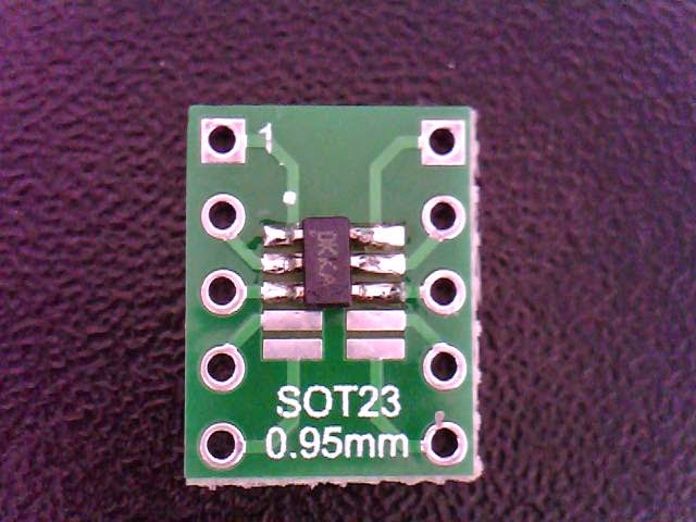
Don’t be scared by the SOT-23 package used, with a small SOT-23 to DIP adapter will fit great in our CBDB extension slots so it will not matter at all. Actually is even more manageable than the MCP9808 Temperature sensor MSOP-8 package used before
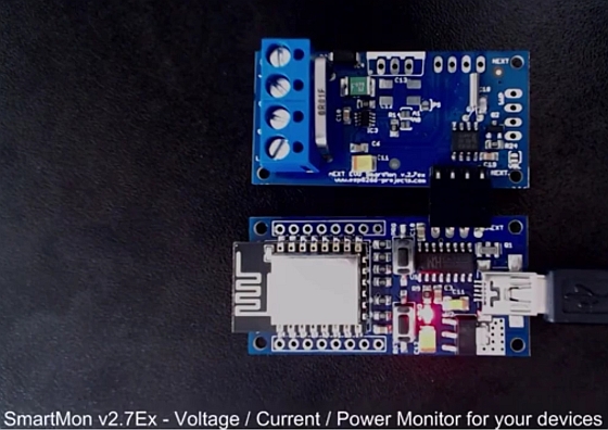
- CBDB Board
- USB adapter (take a look on Part 1 for details how to connect them together)
- MCP4726 Module from above
- LED module (if you want maybe a LED ticker)
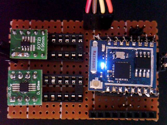 |
| CBDB with MCP4726 DAC and MCP9808 Temperature Modules |
 |
|
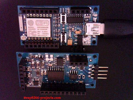
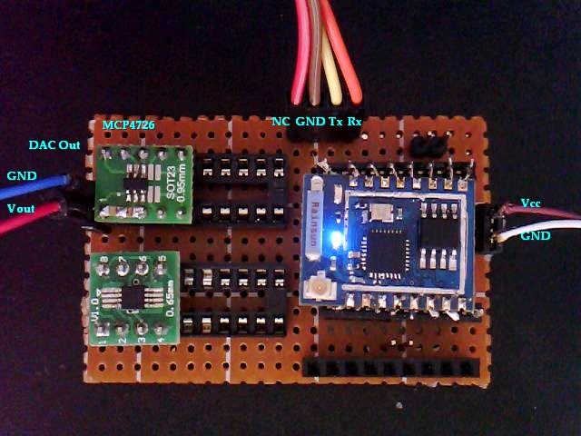
| MCP4726 DAC Module connections |
For programming and uploading the driver and the software we will continue to use the LuaUploader as before.
Driver implementation.
As MCP4726 has a I2C compatible compatible interface, building a driver for it it’s a pretty straigh forward process:
1. Init I2C bus/interface
dev_addr = 0x60,
init = function (self, sda, scl)
self.id = 0
i2c.setup(self.id, sda, scl, i2c.SLOW)
end
2. Write Volatile DAC Register Function.
write_dac = function (self, voltage)
 self.dev_addr = 0x60
 self.reg_addr = 0x40

 volt=(4096*voltage)/3.27 -- tweak the value for your VREF value
 print("Voltage Steps:" .. string.format("%d",volt))  --debug
 msb = bit.rshift(volt, 8)
 print("MSB:" .. string.format("%d",msb))              --debug

 lsb = volt-bit.lshift(msb,8)
 print("LSB:" .. string.format("%d",lsb))              --debug

 i2c.start(self.id)
 i2c.address(self.id, self.dev_addr ,i2c.TRANSMITTER)
 --i2c.write(self.id,self.reg_addr)
 i2c.write(self.id,msb)
 i2c.write(self.id,lsb)
 i2c.stop(self.id)
end
For testing, just save the code on ESP as ‘mcp4726.lua‘, restart ESP and run:
require('mcp4726')
sda=2 --GPIO4
scl=1 --GPIO5
mcp4726:init(sda, scl)
mcp4726:write_dac(1.5)
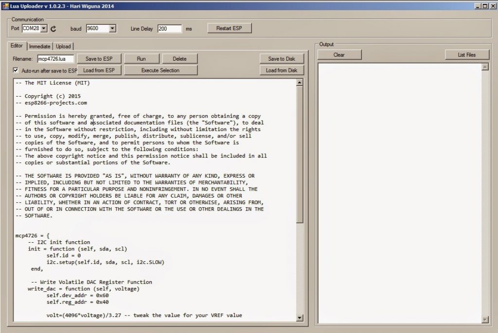
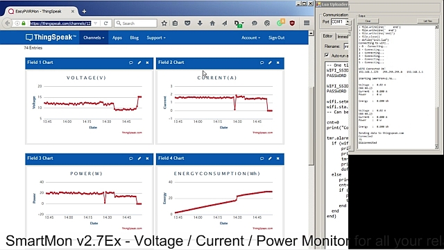
Uploading Driver on ESP module |
|
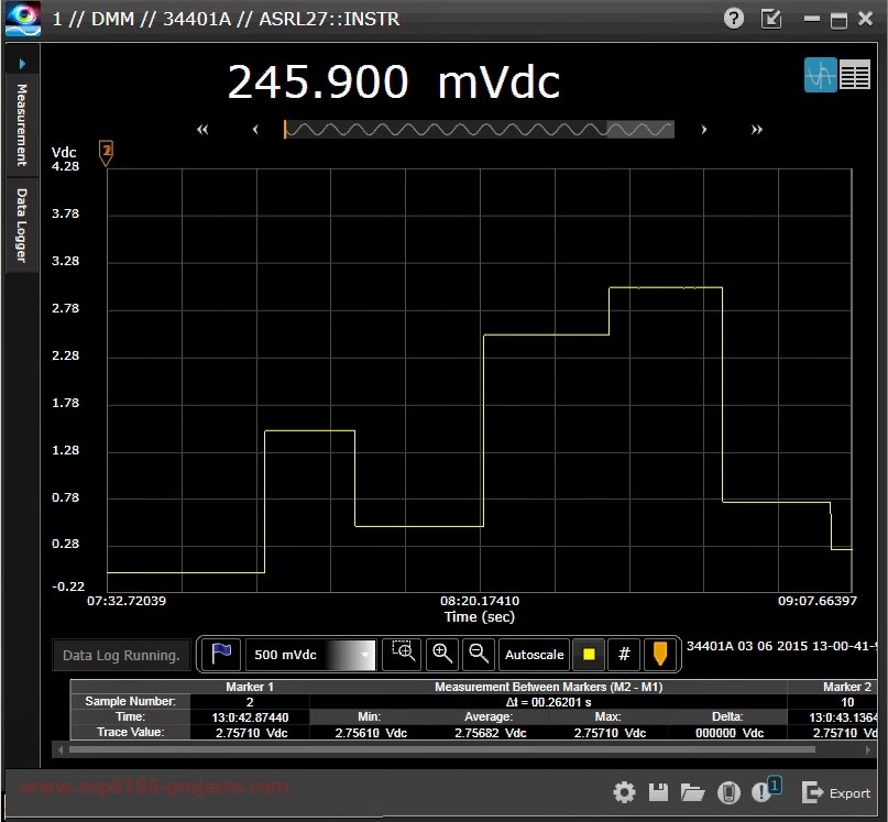
If all OK, if you measure the DAC output (see picture above for connections) you will find the programmed voltage.
 |
|
| MCP4726 DAC output voltage set |
Youtube MCP4726 DAC Driver Test Video :
That’s all for today, thank you for your great feedback and looking forward for your suggestions!