From today we will move on the Analog interface part of the nEXT EVO Board AN-1 and we will start talking about the Digital to Analog conversion, Analog Autoscaling input and Analog to Digital conversion .
For the Digital to Analog conversion part the choosen one is the Microchip MCP4728 I2C DAC IC.
The MCP4728 device is a quad, 12-bit voltage output Digital-to-Analog Convertor (DAC) with non-volatile memory (EEPROM).
As it has a on-board precision output amplifier with rail-to-rail analog output swing capabilities that means first of all that we don’t need any other Output Buffer as mandatory needed for non-buffered DAC’s.
The MCP4728 device has also a high precision internal voltage reference (VREF = 2.048V). The user can select the internal reference or external reference (VDD) for each channel individually.
Features
• 12-Bit Voltage Output DAC with 4 Buffered Voltage Outputs
– Each output is driven by its own output buffer with a gain of 1 or 2 depending on the gain and
VREF selection bit settings.
– In normal mode, the DC impedance of the output pin is about 1Ω. In Power-Down mode,
the output pin is internally connected to 1 kΩ, 100 kΩ, or 500 kΩ, depending on the
Power-Down selection bit settings.
– The VOUT pin can drive up to 1000 pF of capacitive load. It is recommended to use a load
with RL greater than 5 kΩ.
• On-Board Non-Volatile Memory (EEPROM) for DAC Codes and I2CTM Address Bits
• Internal or External Voltage Reference Selection
• Output Voltage Range:
– Using Internal VREF (2.048V):
0.000V to 2.048V with Gain Setting = 1
0.000V to 4.096V with Gain Setting = 2
– Using External VREF (VDD): 0.000V to VDD
• ±0.2 LSB DNL (typical)
• Fast Settling Time: 6 μs (typical)
• Normal or Power-Down Mode
• Low Power Consumption
• Single-Supply Operation: 2.7V to 5.5V
• I2C Interface:
– Address bits: User Programmable to EEPROM
– Standard (100 kbps), Fast (400 kbps) and High Speed (3.4 Mbps) Modes
• 10-Lead MSOP Package
• Extended Temperature Range: -40°C to +125°C
If you want you can consider it the 4 channels big brother of the MCP4726 1 Channel 12 Bit DAC
For more details, please see MCP4728 Datasheet
What we will need:
- ESP8266 nEXT EVO Board
- ESP8266 nEXT EVO – Analog Extension Board – AN1
- For programming and uploading the driver and the software we will continue to use the LuaUploader as before.
 |
| ESP8266 nEXT Evo + Analog Extension AN1 Board |
Driver implementation
As MCP4728 has a I2C compatible compatible interface, building a driver for it it’s a pretty straigh forward process:
1 . I2C Bus initialisation function
function  init_i2c(sda, scl)
          i2c.setup(id, sda, scl, i2c.SLOW)
     end
2. DAC Register Data load
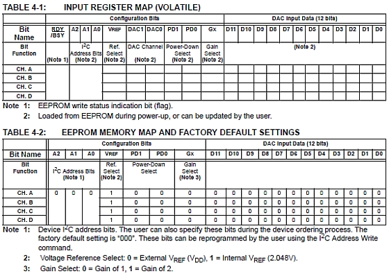
Each channel has its own volatile DAC input register and EEPROM. The details of the input registers and EEPROM are shown in the tables below:
2.1 Simple version using the Power supply Voltage as External
Voltage reference, Vref=Vcc
— single Write command version
 function dac(ch_reg,voltage)
          volt=(voltage*4096)/vcal -- calibrate!
          print("Voltage Steps:" .. string.format("%d",volt))

          msb = bit.rshift(volt, 8)
          print("MSB:" .. string.format("%d",msb))
          lsb = volt-bit.lshift(msb,8)
          print("LSB:" .. string.format("%d",lsb))

          i2c.start(id)
          i2c.address(id, dac_addr ,i2c.TRANSMITTER)
          i2c.write(id,ch_reg)

          i2c.write(id,msb)
          i2c.write(id,lsb)
          i2c.stop(id)
end
2.2 Using the internal Voltage Reference, Vref=2.048V
– Gain settings also enabled, 1x, 2x
 function dac_vref(ch_reg,vref,g,voltage)
          volt=(voltage*4096)/vcal -- calibrate!
          print("Voltage Steps:" .. string.format("%d",volt))

          msb = bit.rshift(volt, 8)
          print("MSB:" .. string.format("%d",msb))
          lsb = volt-bit.lshift(msb,8)
          print("LSB:" .. string.format("%d",lsb))
          if (vref==1) then
                msb = msb + 128
                if (g==2) then msb = msb + 16 end
          end
          i2c.start(id)
          i2c.address(id, dac_addr ,i2c.TRANSMITTER)
          i2c.write(id,ch_reg)

          i2c.write(id,msb)
          i2c.write(id,lsb)
          i2c.stop(id)
end
3. TEST program
3.1 Vref = External, Vref=Vcc
init_i2c(sda,scl)
--SINGLE WRITE COMMAND: WRITE A SINGLE DAC INPUT REGISTER AND EEPROM

ch_reg=0x58         -- CH A - VRef Vcc
dac(ch_reg,0.5)
ch_reg=0x5A        -- CH B - VRef Vcc
dac(ch_reg,1)
ch_reg=0x5C        -- CH C - VRef Vcc
dac(ch_reg,2)
ch_reg=0x5E        -- CH D - VRef Vcc
dac(ch_reg,3)
3.2 Vref = Internal, Vref=2.048V
 -- SET PG to x1 or x2 - valid only when Vref = Vref Internal !!
ch_reg = 0x58
vref= 1    --set internal Vref = 2.048 !!
vcal=2.048
gain=2
voltage = 1
voltage= voltage/2
dac_vref(ch_reg,vref,gain,voltage)
voltage=0.5
dac_vref(ch_reg,vref,gain,voltage)
3.3 Vref = Vcc
-- EXTERNAL Vref = Vcc
 voltage = 2
 gain=1
 ch_reg = 0x58
 vref= 0 -- set EXTERNAL Vref = Vcc = 3.265 - MEASURE & Calibrate!!
 vcal=3.265
 dac_vref(ch_reg,vref,gain,voltage)
–autoupdate DAC every sec
tmr.alarm( 0, 1000, 1, function()
   print("\nUpdate DAC data")
   dac_vref(ch_reg,vref,gain,voltage)
 end)