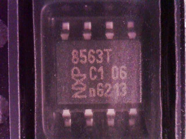
It’s time for TIME!I was delaying this article about RTC’s despite de fact that was higly requested with the hope that the ordered DS3231 modules will arrive in time. Didn’t happen, so, until they will hit my MailBox I am presenting you an alternate solution, an RTC chip used before in many projects without any problems: PCF8563 from NXP.
 |
| PCF8563 – Real-Time Clock (RTC) and calendar |
consumption. A programmable clock output, interrupt output and voltage-low detector are also provided. All addresses and data are transferred serially via a two-line bidirectional I2C-bus with a maximum bus speed of 400 kbit/s.
It is maybe not so fancy as DS3231 but can do the job very well and is way more cheaper that DS3231. Like 1.21$ versus 7-8$ on Digikey. I know they are cheaper DS3231 modules on Ebay but if you want to integrate a RTC on your own projects it’s something mayber to consider.
Features:
• Provides year, month, day, weekday, hours, minutes, and seconds based on a
• Century flag
For more details, please see PCF8563 Datasheet
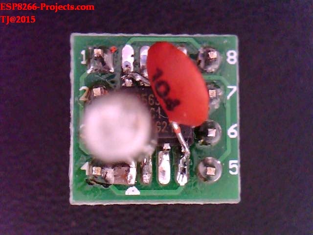
As been available in SO8 package, we will use again an DIP adaptor that will make it easy to integrate it on our CBDB Board expansion slots:
 |
| PCF8563 RTC Module |
Yes, that’s it the entire RTC Module: PCF8563, 32.768khz Quarts cristal oscillator and a decoupling cap. Not bad at all, on a tiny DIP8 size board!
And on the CBDB Board :
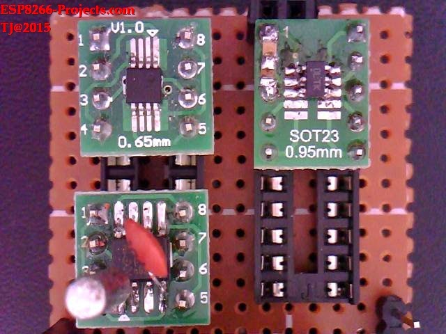
You can see now better the difference between the MSOP8 MCP9808 Temperature sensor, the SO8 PCF8563 RTC and the SOT23 12BIT DAC, MCP4726:
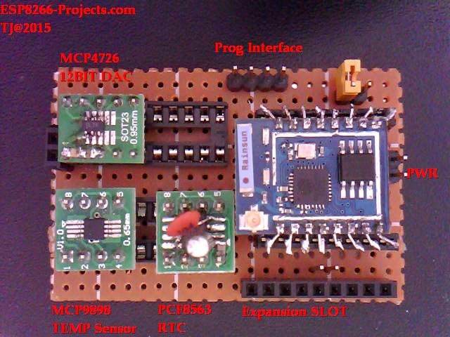 |
| CBDB Board with EXT modules installed |
What we will need:
- CBDB Board
- USB adapter (take a look on Part 1 for details how to connect them together)
- PCF8563 Module from above
For programming and uploading the driver and the software we will continue to use the LuaUploader as before.
Driver implementation
As PCF8563 has a I2C compatible compatible interface, driver building it following more or less the same process as before for I2C devices.
Few important consideration about PCF8563:
The PCF8563 contains sixteen 8-bit registers with an auto-incrementing register address,
an on-chip 32.768 kHz oscillator with one integrated capacitor, a frequency divider which
provides the source clock for the Real-Time Clock (RTC) and calender, a programmable
clock output, a timer, an alarm, a voltage-low detector, and a 400 kHz I2C-bus interface.
All 16 registers are designed as addressable 8-bit parallel registers although not all bits
are implemented. The first two registers (memory address 00h and 01h) are used as
control and/or status registers. The memory addresses 02h through 08h are used as
counters for the clock function (seconds up to years counters). Address locations 09h
through 0Ch contain alarm registers which define the conditions for an alarm.
Address 0Dh controls the CLKOUT output frequency. 0Eh and 0Fh are the Timer_control
and Timer registers, respectively.
When one of the RTC registers is written or read, the contents of all time counters are
frozen. Therefore, faulty writing or reading of the clock and calendar during a carry
condition is prevented.
The Seconds, Minutes, Hours, Days, Months, Years as well as the Minute_alarm,
Hour_alarm, and Day_alarm registers are all coded in Binary Coded Decimal (BCD)
format so we need some BCD to DEC and DEC to BCD functions.
1. Data conversion functions:
1.1 Decimal to BCD:
         function decToBcd(val)
             local d = string.format("%d",tonumber(val / 10))
             local d1 = tonumber(d*10)
             local d2 = val - d1
            return tonumber(d*16+d2)
         end
1.2 BCD to Decimal:
       function bcdToDec(val)
           local hl=bit.rshift(val, 4)
           local hh=bit.band(val,0xf)
          local hr = string.format("%d%d", hl, hh)
          return string.format("%d%d", hl, hh)
     end
2. Init I2C bus/interface:
        address = 0x51, -- A2, A1, A0 = 0
        id = 0
        init = function (self, sda, scl)
               self.id = 0
              i2c.setup(self.id, sda, scl, i2c.SLOW)
       end
    readTime = function (self)
       wkd = {"Sunday", "Monday", "Tuesday", "Wednesday", "Thursday", "Friday", "Saturday" }
       i2c.start(self.id)
       i2c.address(self.id, self.address, i2c.TRANSMITTER)
       i2c.write(self.id, 0x02)
       i2c.stop(self.id)
       i2c.start(self.id)
       i2c.address(self.id, self.address, i2c.RECEIVER)
       c=i2c.read(self.id, 7)
       i2c.stop(self.id)
       return  bcdToDec(bit.band(string.byte(c,1),0x7f)),
               bcdToDec(bit.band(string.byte(c,2),0x7f)),
               bcdToDec(bit.band(string.byte(c,3),0x3f)),
               bcdToDec(bit.band(string.byte(c,4),0x3f)),
               wkd[tonumber(bcdToDec(bit.band(string.byte(c,5),0x7)))],
               bcdToDec(bit.band(string.byte(c,6),0x1f)),
               bcdToDec(string.byte(c,7))
   end
    setTime = function (self, second, minute, hour, day, date, month, year)
       i2c.start(self.id)
       i2c.address(self.id, self.address, i2c.TRANSMITTER)
       i2c.write(self.id, 0x02)
       i2c.write(self.id, decToBcd(second))
       i2c.write(self.id, decToBcd(minute))
       i2c.write(self.id, decToBcd(hour))
       i2c.write(self.id, decToBcd(day))
       i2c.write(self.id, decToBcd(date))
       i2c.write(self.id, decToBcd(month))
       i2c.write(self.id, decToBcd(year))
       i2c.stop(self.id)
   end
 -- Set Initial Time and Date
 require('pcf8563')                                -- call for new created PCF8563 Module Driver
 sda, scl = 2, 1                                      --  declare your I2C interface PIN's
pcf8563:init(sda, scl)                           -- initialize I2C Bus
  pcf8563:setTime(0,34,13,12,4,3,15)   -- setTime(s,min,hour,day,weekday,month, year)
 -- get Time and Date
 require('pcf8563')
 sda, scl = 2, 1
 pcf8563:init(sda, scl)


s, m, h, d, dt, mn, y = pcf8563:readTime()        --ReadTime function call
=string.format("%s - %s/%s/20%s",dt, d, mn, y)
=string.format(" %s:%s:%s", h, m, s)
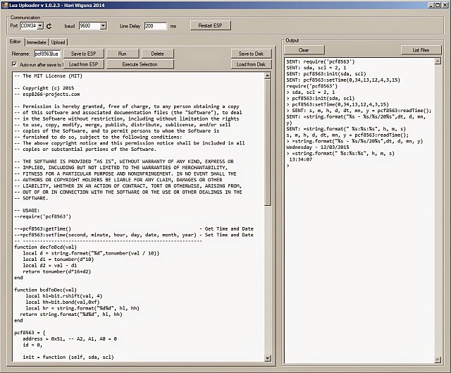
As you have seen above, the RTC can be initialized from the input prompt without problems.
If you want a more automated process to syncronize your Time and Date then you need to look for other options like a NTP Client or to sync it with the Google page help for example. As implementing NTP protocol is a different story itself, let’e see how hard is to pick timestamps from Google page header.
1 Comment
Elmouddene · April 17, 2018 at 9:18 am
Hi there, first I want to thank you for this article and for the huge effort you did put in there. I have a question though, were should I plug the CLKOUT pin in the PCF8563 RTC Module? and what can I use it for?.
Thanks.
Ps: I’m using an ESP12E board.