What do you really expect from a IOT Development board?
I’m sure most of you will say easy configurable Internet access. Direct Wifi if possible.
And after that?
What do you think do you need mostly for your IOT Projects?
Maybe some sort of easy interaction and data exchange with the real world environment?
Sounds intriguing to start with so many questions but they are more than legitimate:
When removing all the bells and whistles, what do we REALLY need to develop the next level of IOT devices?
If you asked yourself already all these questions, and I’m sure a lot of you has done it already, thinking on your own future projects, what do you think about a IOT Development Board that can offer you at least:
- Easy AP/Client Wifi Access
- Easy Firmware Programming
- Easy Software Development
- 18 bit ADC
- 12 bit DAC
- Voltage Measurement
- Current Measurement
- Temperature Measurement
- Real Time Clock
- High Resolution LCD COG Display with direct sunlight reading
- User Definable Buttons
- On Board 3.3V Regulator
Sounds good? sounds impossible? Well…I hope that I have, at least for a part of you, one of the right answers below:
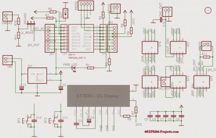 |
| CBDB v2 Schematic |
A DevBoard full of functions in a 5×5 size PCB, small enough to easy integrate in your hobbyist workplace ecosystem 🙂
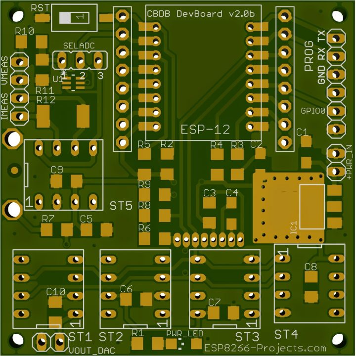 |
| CBDB V2 DevBoard PCB – TOP |
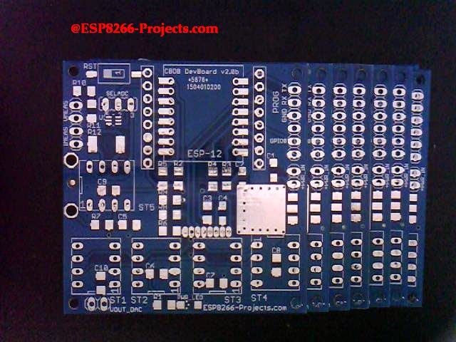
Latest design review PCBs of the fresh new ESP8266 Dev Board v.2 just landed on my desk and is definitely a next step in Experimenting in the IOT world. Designed with ease of use and flexibility in mind it will offer you endless hours of Experimenting, Programming and Developing your own projects.
For any new requests please feel free to use as usual: tech at esp8266-projects.com.
If you want for your own experiments to order CBD v2 EVO bare PCBs only, you can also do it directly at Dirty PCBs, our preferred PCB House:
http://dirtypcbs.com/view.php?share=5876&accesskey=3d0fd70d53d6dc20c0bf0255f67cde65
Please keep in mind this is a experimental board, not a commercial product and is offered as it is. If it will burn your house, help the Aliens to abduct you or even eat your cat it’s your problem not mine. The old enough ones to remember ALF will understand even deeper the disclaimer 🙂
On the TOP side, you can easily directly integrate your LCD or if you want it separate just run it thru a usual cable:
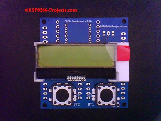 |
| CBDB v2 – TOP |
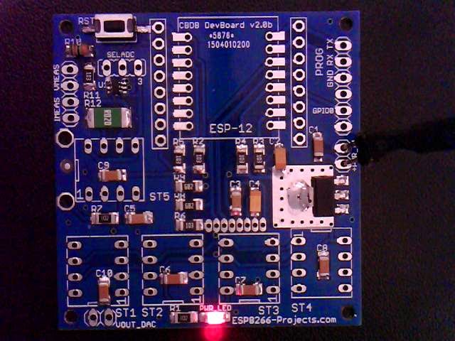
After finished soldering, cleaning and cooling down, this is how is looking the ESP8266 CBDBv2 DevBoard ready for testing the onboard regulator :
Testing was done with power supplied from a Li-Ion Battery pack and also from a standard 5V SMPS unit under a decent 500mA load. No overheating or nasty oscillations, looks good up to 800mA. Are 800mA warm but the proper calculated double side heatsink area is doing the job right :).
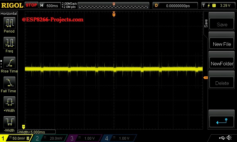 |
| Onboard regulator test – 5V SMPS Supply |
I know it’s a big debate this days about 1A requirement for ESP8266 Modules, but from all my experience and informations, at least with the ESP-07/12 Modules I had in my hands in the latest months, they were never exceed the 250mA margin. In fact, I have one module running for months now as a temperature logger/webserver and the power consumption looks constantly as in the pictures below:
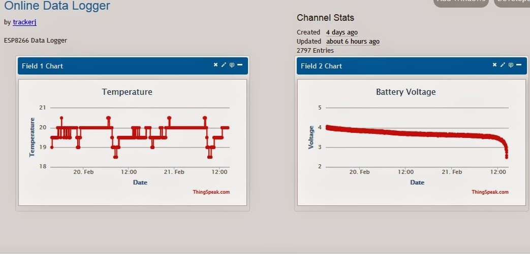 |
| Full drain test with Thinkspeak data upload and 1/s direct web access reload |
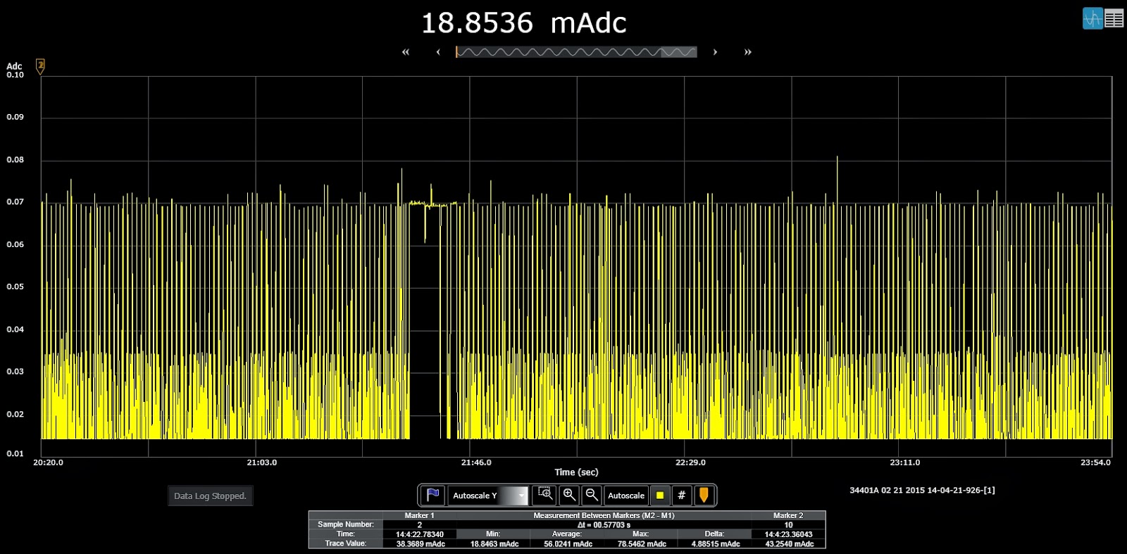 |
| Temperature Logger supply line monitoring |
I must also admit that I have also some old ESP-01 Modules, never used them, they are indeed looking very power hungry but never had the time to check them how much power they require to properly operate. Or if they are just faulty.
I have seen before entire batches of faulty ESP8266 modules. Even ESP-07 ones if you remember the story. What I can confirm about these ESP-01 modules is that they cannot be programmed using power directly from my CP2102 USB Adapter, as ESP-07/12. Not enough juice for them. Why? If I will find some time will take a look at them. If is anybody out there that has the answer, please share it with us.
And finally, this is how is looking, ready for firmware upload and first tests:
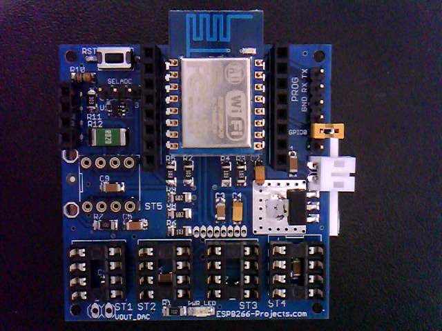 |
| ESP8266 DevBoard |
Stay tuned for what will follow soon: firmware uploading and the infamous Blinky test:)
1 Comment
IOT123 – CHARGER DOCTOR BREAKOUT – Hobby Related News · March 26, 2018 at 2:29 am
[…] I looked at a few MCU based monitors including TJ’s (I later realized I had one of his boards). I remembered I had a few of the CHARGER Doctors lying around, so I created a more versatile […]