If you don’t have any experience and are not qualified for working with MAINS power I will not ecourage you to play arround!
For any new orders / requests please feel free to use as usual: tech at esp8266-projects.com.
If you want for your own experiments to order ESP8266 WIFI Web Power Switch for MAINS – MPSM v.2 DevBoard bare PCBs only, you can also do it directly at Dirty PCBs, our preferred PCB House:
For reference please take a look at the original WIFI MAINS power switch module (MPSMv2) article link:
http://www.esp8266-projects.com/2015/04/p2-wifi-web-power-switch-for-mains-mpsm.html
As you might remember from the previous related article about MPSMv2 Board the software examples were done in NodeMCU LUA.
I was asked to make also a short, basic introduction also for Arduino IDE, so here we go. But before of that I need to make also a short presentation of the MPSMv2 Board with few extra explanations. I will not insist too much on the hardware/schematics/theory of operation part of the story as you have all the details already in the previous articles about, including BOM.
What I want to explain a bit is the concept behind that might help you to understand better how to use the board. To ease the understanding you can see MPSMV2 as 2 separate Boards spliced together, a Breadboard friendly ESP8266 adapter with integrated 3.3V Power Supply, and a MAINS Triac Switch.
The PCB is designed in such way that no harm will be done by cutting it in half as in the below picture.
 |
|
| MPSMv2 Board – Full and splitted |
You can use separatelly the 2 parts, the ESP8266 Adapter with 3V3 regulator and the Triac MAINS Power Switch.
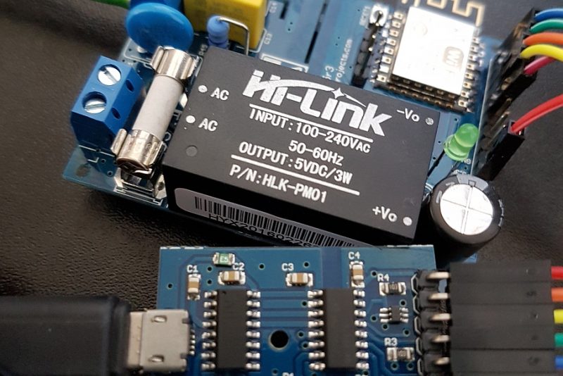
 |
| MPSMv2 – ESP8266 adapter with voltage regulator & stuff on the back |
The Triac Switch part can be used directly even with a different ARM, PIC, Arduino, whatever MCU you have arround without any problems as long as it has a GPIO pin capable to drive the MOC Optocoupler LED thru CMD port.
 |
| Triac Driver part – use proper Fuse and EMI filtering! |
Please keep in mind that de design was done in such a basic way as been designed to be part of a bigger system and used for development and testing.
Please use propper MAINS protection, FUSE and EMI filtering block based on your specific application requirements!
There were a lot of questions and debates about, including the Hackaday one, why it has not a FUSE, where is the filtering, etc, etc … they are not there because should not be there in our MPSMv2 design.
Input protection/filtering block for MAINS should not be on the same board with the driver. They are a lot of explanations behind this but even only having more flexibility in mind should suffice.
If you look at the EMI filter below, similar with the choosen one as suitable to be used in our project you will understand even more why should be not on the MPSMv2 board.
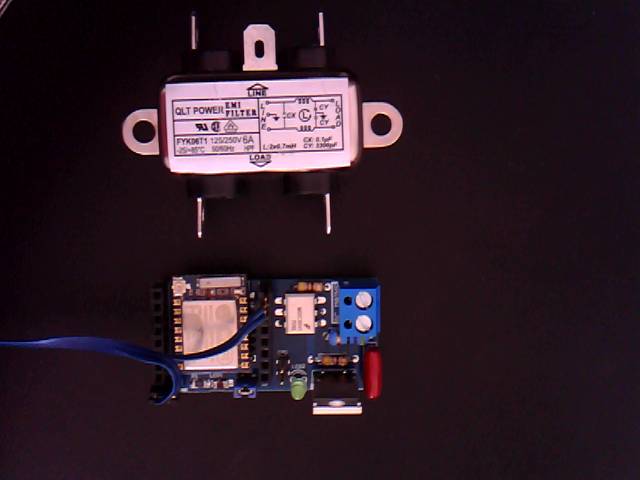 |
| EMI filter vs. MPSMv2 Board |
Now let’s go back to our main story for today: how to use MPSMv2 with Arduino IDE.
What we will need:
- MPSMv2 DevBoard
- USB adapter
- For programming MPSM v2 DevBoard we will use Arduino IDE
1. Software installation
If you didn’t have yet installed a proper running ESP8266 Arduino IDE environment the ESP8266 Arduino IDE installation Article might help you. Or the Youtube video from below:
2. Wiring
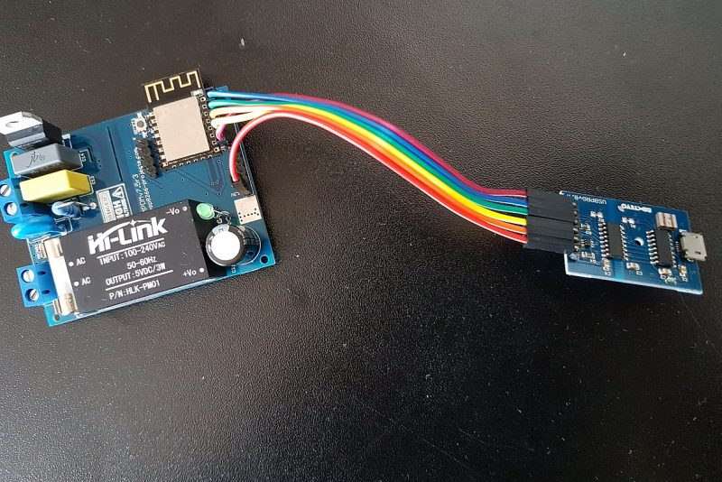
Connect the MPSMv2 Module to the USB adapter as in the picture below:
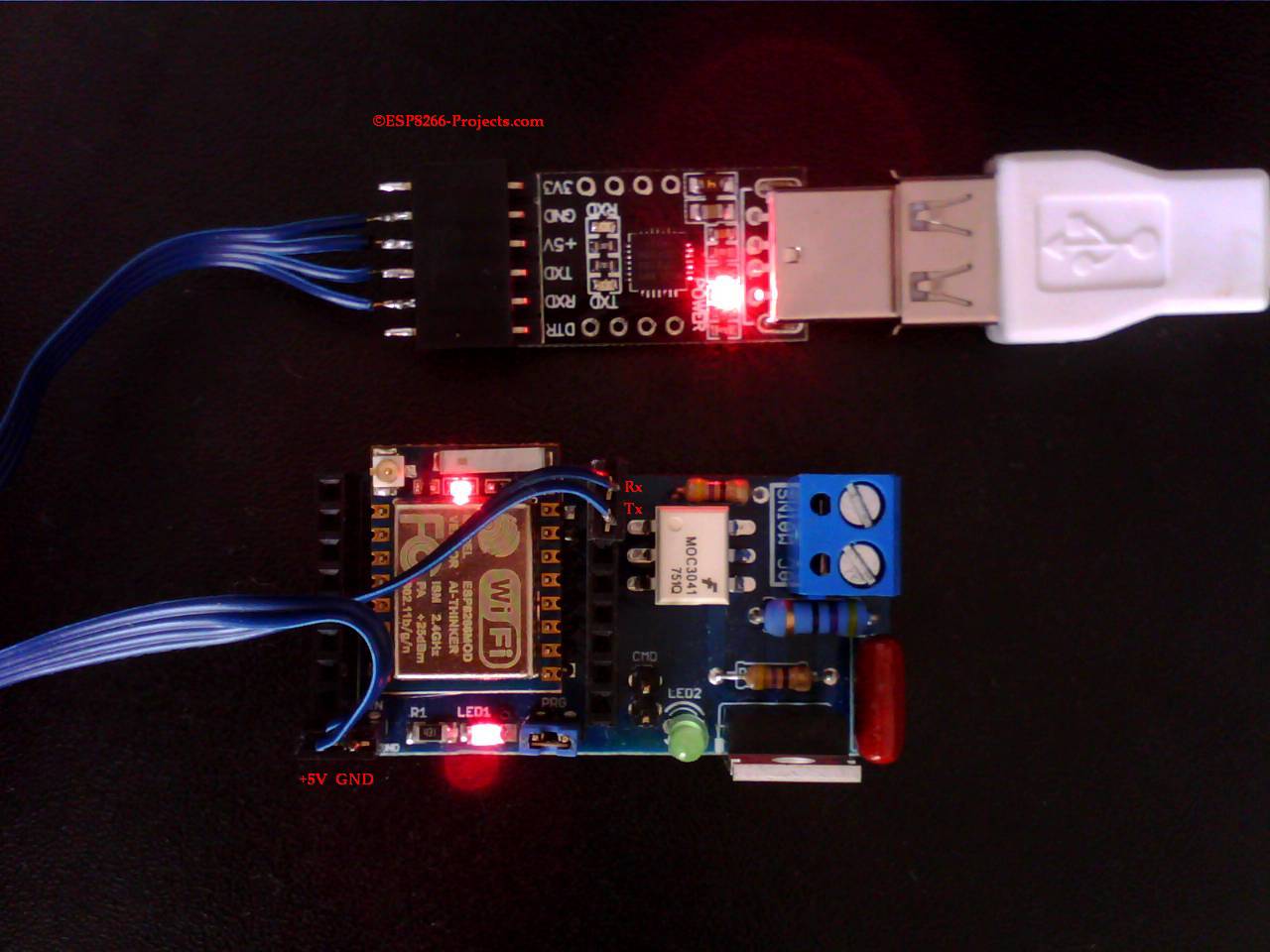 |
| MPSMv2 – USB Adapter Wiring |
USB MPSMv2
Rx -> Tx
Tx -> Rx
GND -> GND
+5V -> Power input port +5V
Set the PRG jumper (Blue) for programming mode ON !
3. Arduino IDE Programming.
- Start Arduino IDE
- Select inside IDE your desired ESP8266 Board (default one should be also OK).
- Plug-in the USB adapter connected with the MPSMv2 module as above, will see the power on LED’s
- Open in IDE the basic Blink program
- Replace the digital pin 13 as an output PIN with1.
- Compile and upload the program to MPSMv3 board.
The result:
Let’s test also the Triac driver command pin:
Q & A :
- How can you have more than a MAINS power switch channel available? Very simple: just cut the Triac driver part from other MPSMv2 PCB’s and connect the Driver side only to the full size MPSMv2 Board.
- How many independent MAINS lines can be driven by a single MPSMv2 Board? As many as free IO pins you have available in your project and Triac Drivers you might add to it.
- What’s the easiest way to have 2 MAINS lines swiched synchronous? Just connect the CMD port from a second available Triac module to the CMD port on the main MPSMv2 Triac Module. The Triac driver from the MPSMv2 will be commanded in sync with the second connected one.