AVAILABLE also on TINDIE Store : https://www.tindie.com/stores/nEXT_EVO1/
Today we will continue with the most requested typer os posts the “Driver Implementation Series”: Part 1 of the PCF8575 16-bit I/O Port Expander – Output.
In the situation when you need more I/O pins that available on your MCU the simplest solution is to use a “port expander”. In the previous articles, nEXT EVO Extension Board AN1 (for I/O output) and 4×4 Matrix Keyboard input example for ESP8266 (for I/O input), we spoken already about a 8 bit I/O port expander based on the PCF8574 IC from NXP.
But what to do if you need for your project even more I/O lines?
You have 2 solution:
1. Use more that one PCF8574, configure each with it’s own unique I2C address.
2. For higher density number of I/O pins os just a compact 16 I/O lines interface, use the bigger brother of the PCF8574, the PCF8575.
As the option (1) I think is obvious for everybody and means just replication of the PCF8574 as many times you need it (and have free available I2C addresses for each), today we will explore a bit the 16bit version, the PCF8575.
PCF8575 General Description
The PCF8575 is a silicon CMOS circuit, and provides general purpose remote I/O expansion for most microcontroller families via the two-line bidirectional bus (I²C-bus).
The device consists of a 16-bit quasi-bidirectional port and an I²C-bus interface (PCF8574 has 8-bit one).
The PCF8575 has a low current consumption and includes latched outputs with high current drive capability for directly driving LEDs.
It also possesses an interrupt line (INT) which can be connected to the interrupt logic of the microcontroller. By sending an interrupt signal on this line, the remote I/O can inform the microcontroller if there is incoming data on its ports without having to communicate via the I²C-bus.
And here you can see the advantage over using 2xPCF8574. For each of the 16 I/O lines you can use just one INT line to your MCU. In case of the PCF8574 usage you need 2 INT lines. So, less overhead on number of the I/O lines.
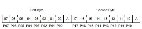
Every data transmission from the PCF8575 must consist of an even number of bytes, the first byte will be referred to as P07 to P00 and the second byte as P17 to P10. The third will be referred to as P07 to P00 and so on.
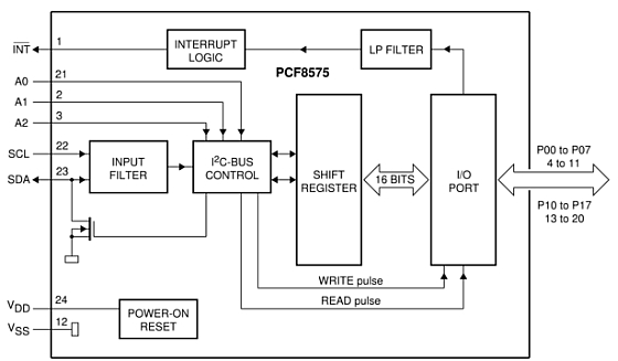 |
| PCF8575 – Block Diagram |
Features
- Operating supply voltage 2.5 to 5.5 V
- Low standby current consumption of 10 µA maximum
- I²C-bus to parallel port expander
- 400 kbits/s FAST I²C-bus
- Open-drain interrupt output
- 16-bit remote I/O port for the I²C-bus
- Compatible with most microcontrollers
- Latched outputs with high current drive capability for directly driving LEDs
- Address by 3 hardware address pins for use of up to 8 devices
- SSOP24 package.
As been very similar with his small brother, the PCF8575, described already, I will not insist too much on the IC itself, for a deeper look please take a look also at the Datasheet.
What we will need:
- ESP8266 nEXT EVO Board
- PCA9685 Extension Board as below or similar
- For programming and uploading the driver and the software we will continue to use the LuaUploader as before.
Connection with the ESP8266 nEXT EVO Board is very easy, as PCF8575 Extension Board connector is fully compatible with the nEXT connector. Depending on how to you choose you socket type, you can install it on TOP or Bottom of the ESP8266 nEXT EVO Board :
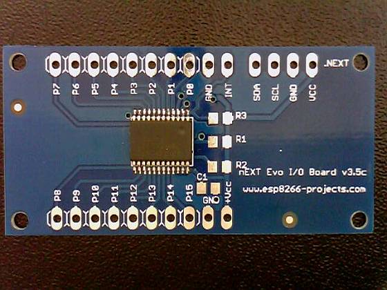 |
| PCF8575 – nEXT EVO 16bit Expander Board – TOP |
On the bottom side you can see also available the jumpers for I2C address selection in case that you need more than one I/O Expander board connected in the same time:
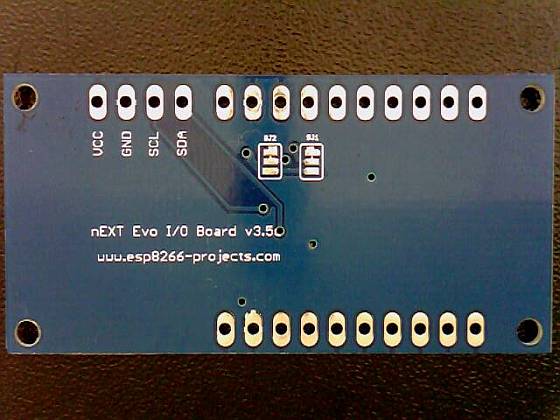 |
| PCF8575 – nEXT EVO 16bit Expander Board – Bottom |
Driver implementation
As PCF8575 is a I2C device, building a driver for it will follow the same path as for any other I2C compatible device:
1 . I2C Bus initialisation function
function init_i2c(sda, scl)
i2c.setup(id, sda, scl, i2c.SLOW)
end
2 . PCF8575 Write register function (for data Output)
To write, the master (microcontroller) first addresses the slave device. By setting the last bit of the byte containing the slave address to logic 0 the write mode is entered.
The PCF8575 acknowledges and the master sends the first data byte for P07 to P00. After the first data byte is acknowledged by the PCF8575, the second data byte P17 to P10 is sent by the master. Once again the PCF8575 acknowledges the receipt of the data after which this 16-bit data is presented on the port lines.
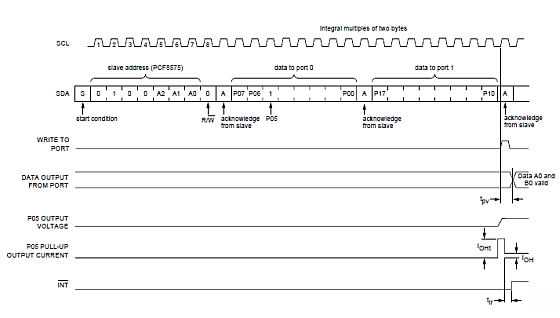
The number of data bytes that can be sent successively is not limited. After every two bytes the previous data is overwritten.
The first data byte in every pair refers to Port 0 (P07 to P00), whereas the second data byte in every pair refers to Port 1 (P17 to P10):
function setPort( port, PL, PH)
     i2c.start(id)
     i2c.address(id, io_addr,i2c.TRANSMITTER)
     i2c.write(id,PL)
     i2c.write(id,PH)
     i2c.stop(id)
 end
3 . PCF8575 Set Port (for data Output)
function setPortdata(pl, ph)
    ppl = 255-pl
    pph = 255-ph
    setPort(0x20,ppl, pph)
end
4 . Main program
id = 0                    --I2C bus ID
sda=2                    --GPIO4
scl=1                     --GPIO5
io_addr = 0x20     --PCF8575 I2C Address

--init I2C nEXT BUS
i2c_init()
 -- Direct port bit set examples
 setPortdata(0,0)   -- All OFF
setPortdata(1,0) -- P0 - ON setPortdata(2,0) -- P1 - ON setPortdata(4,0) -- P2 - ON setPortdata(8,0) -- P3 - ON setPortdata(16,0) -- P4 - ON setPortdata(32,0) -- P5 - ON setPortdata(64,0) -- P6 - ON setPortdata(128,0) -- P7 - ONsetPortdata(0,1) -- P8 - ON setPortdata(0,2) -- P9 - ON setPortdata(0,4) -- P10 - ON setPortdata(0,8) -- P11 - ON setPortdata(0,16) -- P12 - ON setPortdata(0,32) -- P13 - ON setPortdata(0,64) -- P14 - ON setPortdata(0,128) -- P15 - ON