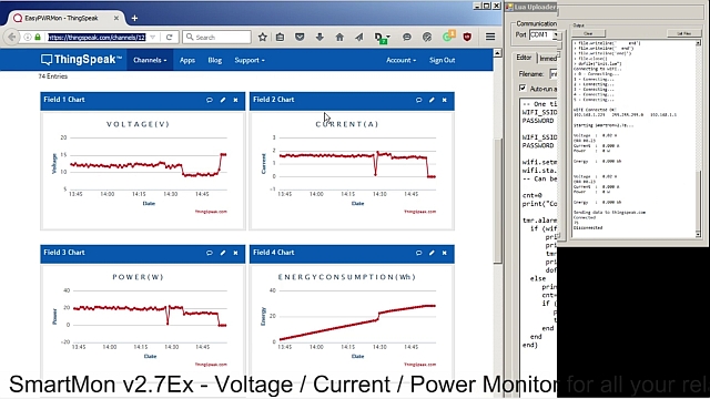
 |
| Autorange Analog frontend |
For a deeper Hardware description please take a look at the ESP8266 Analog Extension Board
What we will need:
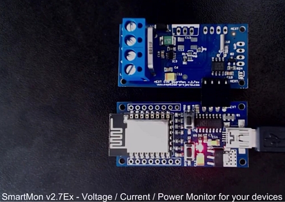
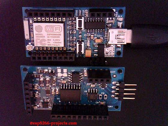
- ESP8266 nEXT EVO Board
- ESP8266 nEXT EVO – Analog Extension Board – AN1
- For programming and uploading the driver and the software we will continue to use the LuaUploader as before.
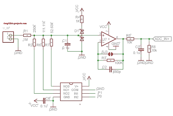
ADC Frontend description
Selection of the input voltage divider is done using an analog switch driven by PCF8574 PORT P0 and P1 bits:
0 – 1:20 Divider
1 – 1:10 Divider
2 – 1:5 Divider
3 – Full Voltage Range
As the ADC Input is programmed to be used in the 0-2V range that will give us the followings available ranges:
0 -> 0 – 40V
1 -> 0 – 20V
2 -> 0 – 10V
3 -> 0 – 2V
In the case of using the MCP3421 ADC at 12 Bit resolution, we will have the following corresponding LSB values:
– 1:20 Divider – 0.02V
– 1:10 Divider – 0.01V
– 1:5 Divider – 0.005V
– Full Range – 0.001V
Software implementation
1. Init I2C bus/interface
Standard I2C Bus Initialisation function:
function init_I2C()
    i2c.setup(bus, sda, scl, i2c.SLOW)
end
function setPort( port, stat)
    i2c.start(id)
    i2c.address(id, dev_addr ,i2c.TRANSMITTER)
    i2c.write(id,stat)
    i2c.stop(id)
end
3. Set Port function Just a nicer way to write data to PCF8574 Register. Remember that we need to write a “ZERO” to the corresponding bit. We are sinking not sourcing !!
function setPortdata(p)
    pp = 255-p
    setPort(0x20,pp)
end
4. Set Voltage Divider function
Select the desired Voltage divider ratio based on the choosen ratio value and calibrated LSB data.
--calibration data
x20 = 0.020056
x10 = 0.01014
x5  = 0.005014
xfl = 0.0010075
xrt = x20 --by default start with highest VDIV!
function SetVDivider(rtio)
    if (rtio==0) then xrt=x20 end
    if (rtio==1) then xrt=x10 end
    if (rtio==2) then xrt=x5 end
    if (rtio==3) then xrt=xfl end
    print("XRT = "..xrt)
    setPortdata(rtio)    -- select desired voltage divider
    return xrt
end
4.1 Set/Change Voltage Divider ratio:
SetVDivider(0)  -- 1:20 Divider
 SetVDivider(1)  -- 1:10 Divider
 SetVDivider(2)  -- 1:5  Divider
 SetVDivider(3)  -- 1:1  Full Voltage in!!
5. MAIN Program
-- Main Program
id = 0
sda=2 --GPIO4
scl=1 --GPIO5
dev_addr = 0x20

--calibration data
 x20 = 0.020056
 x10 = 0.01014
 x5  = 0.005014
 xfl = 0.0010075
 xrt = x20 --by default start with highest VDIV!

--init I2C Bus
init_I2C()

--Init Volatage divider
setPortdata(0) -- --by default start with highest VDIV!
SetVDivider(0)  -- 1:20 Divider

----MCP3421 ADC
require('mcp3421')
sda=2 --GPIO4
scl=1 --GPIO5
mcp3421:init(sda, scl)
mcp3421:write_ADC_config(0x68, 0x10)

tmr.alarm( 0, 1000, 1, function()
    adc_val = mcp3421:read_ADC_data(0x68)
    print("\nADC Value : "..adc_val.." \n Voltage  : " ..adc_val*xrt)
    return adc_val
end)