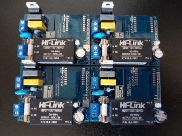
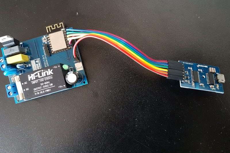
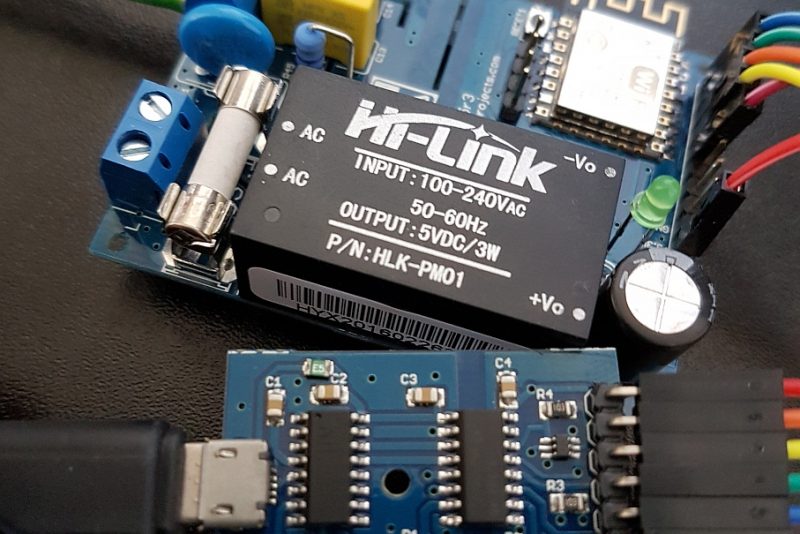
For a more detailed description please take a look at the Part 1: MPDMv7.5 AC Dimmer devboard overview
MPDMv7.5 AC Dimmer devboard is also available on Tindie Store
A very simple MPDMv7.5 Arduino IDE driver example:
const int vcntPin = 13; // the pin that the MPDMv4 VCNT pin is attached to
const int ON = 16; // digital ON/OFF pin
byte brightness = 75; // Brightness value (VCNT)
 // 10-bit resolution for PWM: 0->1023
 // VCNT defined interval: 0->850

void setup()
{
 // initialize the serial communication + NO LINE ENDING:
 Serial.begin(9600);
 // initialize the ledPin as an output:
 pinMode(vcntPin, OUTPUT);
 // initialize digital ON/OFF pin as an output.
 pinMode(ON, OUTPUT);
 // set default brightness value
 analogWrite(vcntPin, brightness);

//default Dimmer ON
 digitalWrite(ON, HIGH); // turn the AC Dimmer ON (HIGH is the voltage level)
 delay(500); // wait for 1/2 second

//default Dimmer OFF
// digitalWrite(ON, LOW); // turn the AC Dimmer OFF by making the voltage LOW
// delay(500); // wait for a second

Serial.println("MPDMv7.5 init done.\n Input your dimming level (1-89) ");

}

void loop() {

// check if data has been sent from the computer:
 if (Serial.available()) {
 // read the most recent byte (need to be from 1 to VCNT MAX (89 for 105W ECO Halogen lightbulb, 240VAC/50Hz)) + NO LINE ENDING!
 brightness = Serial.parseInt();
 Serial.print("Command received : ");
 Serial.println(brightness);

// set the brightness of the lightbulb:
 if (brightness > 89)
 {
 brightness = 89; //define your own upper VCNT voltage control interval here
 }

if (brightness == 0) //turn OFF
 {
 digitalWrite(ON, LOW); // turn the AC Dimmer OFF by making the voltage LOW
 // delay(500); // wait for 1/2 second
 }
 else
 {
 analogWrite(vcntPin, brightness*10);
 digitalWrite(ON, HIGH); // turn the AC Dimmer ON (HIGH is the voltage level)
 //delay(500); // wait for 1/2 second
 }
 }
}
2 Comments
oori · April 12, 2018 at 1:03 pm
Thanks. Would be happy to see:
1. Extended version with 12bit DAC and ESP8266
2. Your Arduino’s board settings (assuming USBProg).
oori · April 12, 2018 at 1:30 pm
I’ll reply myself to #1:
—-
#include
const int i2cAddress = 96;
void setup() {
Wire.begin();
}
void dim(float v) {
int cmdv = (4096*v);
int cmdh = cmdv >> 8;
int cmdl = cmdv – ( cmdh << 8 );
Wire.beginTransmission(i2cAddress);
Wire.write(cmdh);
Wire.write(cmdl);
Wire.endTransmission();
}
—-