|
Today subject might look a trivial one but is not. At all. I will try to keep it as easy to understand as possible without too much “behind the scene” theory. Contact bounce is a common problem with mechanical and electromecanical switches, relays, solenoids, etc. But what happens during the bounce? Every bounce of every switch is different, a non deterministic function, a totally random event. Many produce only high speed hash till a solid one or zero appeared. Others can generate a serious pulse train of discernible logic levels that can give nightmares to the most sophisticated software debounce routine.
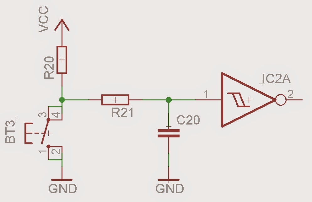
The effect is usually unimportant in power circuits, but causes problems in some analogue and logic circuits that respond fast enough to misinterpret the on‑off pulses as a data stream or change of the input logic level. They are many options and techniques that can solve this problem, some of them software based, some pure hardware. Few examples: 1. RC Filter Debouncing The RC filter slows down the signal transitions generated by the switch so the each button press gives one slow edge. It is usually best to follow the RC filter stage with a Schmitt trigger buffer. Schmitt Trigger, which is simply an inverter equipped with hysteresis, further limits the switch bouncing.
2. Hardware – Dedicated Integrated Circuits Another way to debounce switches in hardware is to take advantage of application-specific integrated circuits. Semiconductor manufacturers such as Maxim Integrated offer switch debouncers like the MAX6816 in very small packages, with built-in ESD protection. These parts cost a few dollars, depending on the purchasing volume. Digikey example : MAX6816. Although they are extremely easy to use, they are more expensive and offer less flexibility than a custom tailored solution. 3. Software routines, time delay This is accomplished by inserting, depending of the pushbutton behaviour, a 20 to 50ms lockout delay in the function responding to port pin changes. The delay prevents the MCU from responding to the multiple switch transitions related to bouncing. The value should be choosen in such a way that is not affecting the true, real, switch transitions created by a true switch event. Maximum desired valid switching speed should also be determined for proper defining of the process. From my experience I think the best option is a combination of both Hardware and Software sides, so, what we will study it’s a combined solution, a First order Low Pass Filter implemented in Hardware combined with Software Interrupt trigger routines on falling/rising edge. It’s a simple setup and the results are great. Don’t understand it wrong: it’s no technique or solution for a piece of crap contact! What I have learned after some horror stories with switches and push buttons is that no matter the supplier, spend 5-10-15 minutes, take few from the batch, study their behavior and characterize them on the Oscilloscope! It’s a truly life saver, no joke at all! Let’s continue with our choosen option. What we will need:
For programming and uploading the driver and the software we will continue to use the LuaUploader as before. 1. HARDWARE
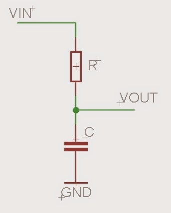
One simple low-pass filter circuit consists of a resistor in series with a load, and a capacitor in parallel with the load. The capacitor exhibits reactance, and blocks low-frequency signals, forcing them through the load instead. At higher frequencies the reactance drops, and the capacitor effectively functions as a short circuit. The combination of resistance and capacitance gives the time constant of the filter:  The break frequency, also called the turnover frequency or cutoff frequency (in hertz), is determined by the time constant: 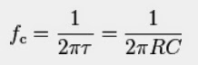 or equivalently (in radians per second): This circuit may be understood by considering the time the capacitor needs to charge or discharge through the resistor:
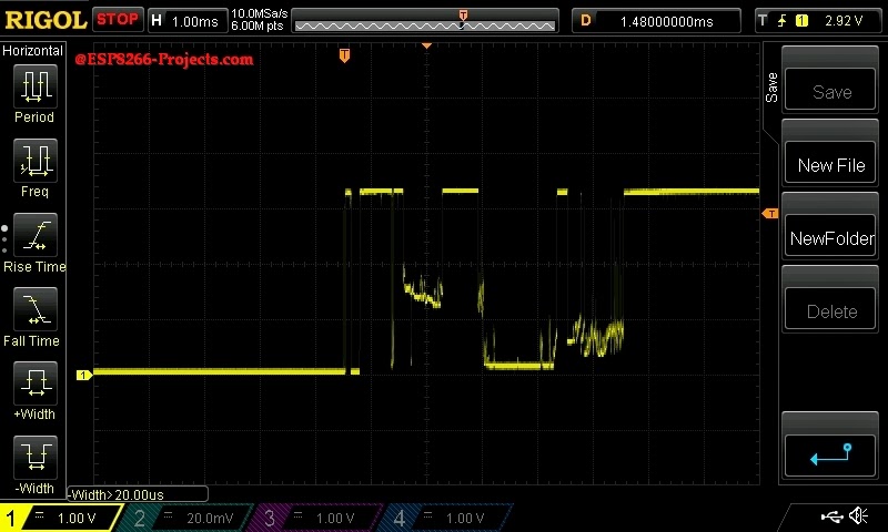
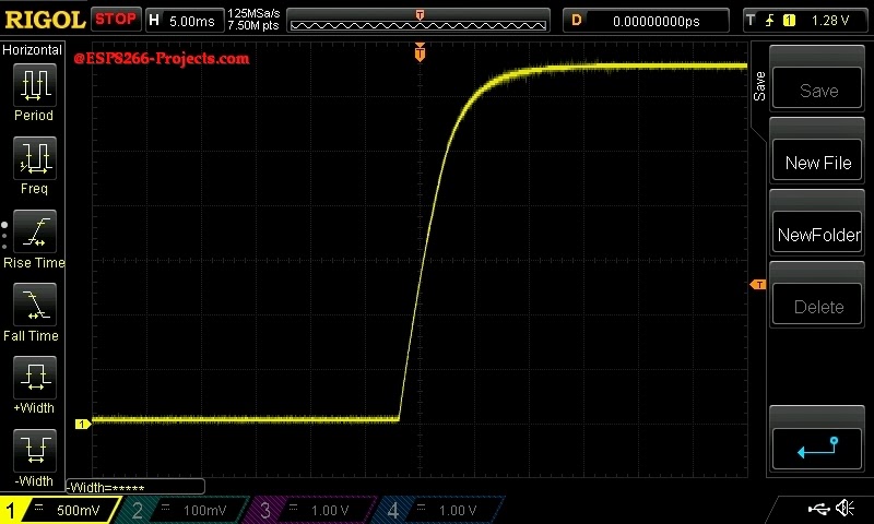
Let’s see on the Osciloscope how the value of the capacitor C can affect the rising time and what’s the effect on the boucing event.
So, how big should be the capacitor C? It really depends on the specific application and also a lot on the quality of the pushbutton contacts but for a decent quality human pressed pushbutton a value between 10nF and 100nF might be the answer. 2. SOFTWARE 2.1 Init stat="No key press" -- initial status outpin=3 -- Select output pin - GPIO0 gpio.mode(outpin,gpio.OUTPUT) inpin=6 -- Select input pin - GPIO12 gpio.mode(inpin,gpio.INT,gpio.PULLUP) -- attach interrupt to inpin, activate internal PULLUP 2.2 Trigger functions
This 2 functions below are the interrupt callback functions used for push button status detection. A small delay added to “smooth” even more the readout from the pushbutton. Most of the time not necessary as the RC filter combined with the smart change of the trigger activation from falling/rising edge is enough. As this time we use the “Ugly Bouncing Button” (see picture above – worst case scenario) extra delay is added. 2.2.1 Trigger functions function pressed()
print("Key Pressed!") -- print status
st7032i:lcd_setCursor(1,1) -- set cursor pos LCD
st7032i:lcd_write("Key Pressed!") -- print status LCD
stat = "ON"
gpio.write(outpin,gpio.HIGH) -- Led ON - Motion detected
tmr.delay(10) -- time delay for switch debounce
gpio.trig(inpin,"up",released) -- change trigger on falling edge
return stat
end
  function released()
       print("Key Released!")
       st7032i:lcd_setCursor(1,1)
       st7032i:lcd_write("Key Released!")
       stat = "OFF"
       gpio.write(outpin,gpio.LOW)   -- Led OFF
       tmr.delay(10)
      gpio.trig(inpin,"down",pressed)  -- trigger on rising edge
      return stat
  end
For testing, just save the code on ESP as ‘button_test.lua‘, restart ESP and run: -- INIT LCD
require('st7032i') -- I suppose you have already uploaded st7032i module from previous articles
sda, scl = 2, 1
st7032i:init_i2c(sda, scl)
st7032i:init_LCD()
require('button_test') --call for new created button Module
gpio.trig(inpin,"down",pressed) -- trigger activated on rising edge

|


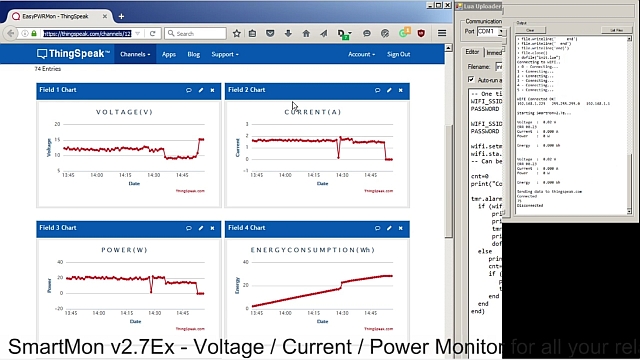
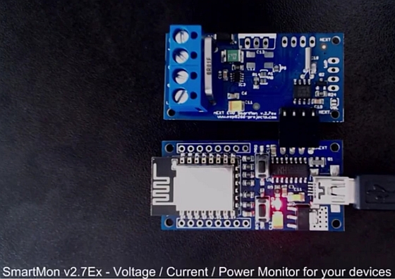
battery monitor system
Thingspeak – SmartMon Ext Board P4
This is Part 4 of the SmartMon Extension Board series. SmartMon v2.7ex Board is a extension board fully compatible with Arduino, ESP8266, ARM, PIC & other available MCu’s out there. As long as your MCU/Dev Read more…