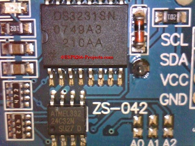
As you remember from our previous article about DS3231 RTC Module, we have identified onboard an EEPROM chip, a 32k AT24C32 one. It is independent from the RTC circuit and conected on the I2C bus, perfect companion for a Data Logger System 🙂
 |
|
| AT24C32 EEPROM |
The AT24C32 provides 32,768 bits of serial electrically erasable and programmable read only memory (EEPROM) organized as 4096 words of 8 bits each. Might not sound too much but believe it or not you can log 6 months of data or even more on it depending on your application requests and how you organize your data logging.
For example if you save your data in 1byte, you will have enough for around 170 days or 24 weeks! With an added 16 extra location available for bulding data header/date/time/CRC/whatever your needs ask for. And if you still feel it to small, you can use anytime AT24C64, 64k size (8192 x 8), direct drop-in replacement!
Also the device’s cascadable feature allows up to 8 devices to share a common I2C bus. The device is optimized for use in many industrial and commercial applications where low power and low voltage operation are essential. In addition, the entire family is available in 2.7V (2.7V to 5.5V) and 1.8V (1.8V to 5.5V)versions.
FEATURES:
• Low-Voltage and Standard-Voltage Operation
– 2.7 (VCC = 2.7V to 5.5V)
– 1.8 (VCC = 1.8V to 5.5V)
• Low-Power Devices (ISB = 2μA at 5.5V) Available
• Internally Organized 4096 x 8
• 2-Wire Serial Interface
• Schmitt Trigger, Filtered Inputs for Noise Suppression
• Bidirectional Data Transfer Protocol
• 100 kHz (1.8V, 2.5V, 2.7V) and 400 kHz (5V) Clock Rate
• Write Protect Pin for Hardware Data Protection
• 32-Byte Page Write Mode (Partial Page Writes Allowed)
• Self-Timed Write Cycle (10 ms max)
• High Reliability
– Endurance: 1 Million Write Cycles
– Data Retention: 100 Years
• Automotive Grade and Extended Temperature Devices Available
• 8-Pin JEDEC PDIP, 8-Pin JEDEC SOIC, 8-Pin EIAJ SOIC, and 8-pin TSSOP Packages
For more details please see AT24C32 Datasheet
What we will need:
- CBDB Board
- USB adapter (take a look on Part 1 for details how to connect them together)
- DS3231 Module from previous article
For programming and uploading the driver and the software we will continue to use the LuaUploader as before.
Driver implementation
To be able to access and properly operate with any kind of memory devices we need at least 3 basic functions implemented: addressing, read and write. Plus the proper I2C/SPI/Whaterver bus communication initialisation, ofcourse.
1. Init I2C bus/interface:
         address = 0x50,                         -- A2, A1, A0 = 0
        id = 0

        init = function (self, sda, scl)
               self.id = 0
              i2c.setup(self.id, sda, scl, i2c.SLOW)
       end
ADDRESSING:
The 32K EEPROM requires an 8-bit device address word following a start condition
to enable the chip for a read or write operation.
It uses the three device address bits A2, A1, A0 to allow as many as eight
devices on the same bus. These bits must compare to their corresponding hardwired
input pins. The A2, A1, and A0 pins use an internal proprietary circuit that biases them
to a logic low condition if the pins are allowed to float.
The eighth bit of the device address is the read/write operation select bit. A read operation
is initiated if this bit is high and a write operation is initiated if this bit is low.
2. WRITE Function
A write operation requires two 8-bit data word addresses following the device address word and acknowledgment. Upon receipt of this address, the EEPROM will again respond with a zero and then clock in the first 8-bit data word. Following receipt of the 8-bit data word, the EEPROM will output a zero and the addressing device, such as a microcontroller, must terminate the write sequence with a stop condition.
At this time the EEPROM enters an internally-timed write cycle, tWR, to the
nonvolatile memory. All inputs are disabled during this write cycle and the EEPROM will
not respond until the write is complete
    write_EEPROM = function (self, devadr, memadr, edata)
       i = 1
       length = string.len(edata)
       adrh=bit.rshift(memadr, 8)
       adrl=bit.band(memadr,0xff)
       i2c.start(self.id)
       i2c.address(self.id, self.address, i2c.TRANSMITTER)
       i2c.write(self.id, adrh)
       i2c.write(self.id, adrl)
       --print(edata)                               --debug only
       --print(string.byte(edata,1))        --debug only
       while i<=length do
          tmr.wdclr()
          i2c.write(self.id,string.byte(edata,i))
          i = i+1
       end
       i2c.stop(self.id)
   end
3. READ Function
A random read requires a “dummy” byte write sequence to load in the data word address. Once the device address word and data word address are clocked in and acknowledged by the EEPROM, the microcontroller must generate another start condition.
The microcontroller now initiates a current address read by sending a device address with the
read/write select bit high. The EEPROM acknowledges the device address and serially clocks
out the data word. The microcontroller does not respond with a zero but does generate a following
stop condition
        read_EEPROM = function (self, devadr, memadr, length)
            adrh=bit.rshift(memadr, 8)
            adrl=bit.band(memadr,0xff)
            i2c.start(self.id)
            i2c.address(self.id, self.address, i2c.TRANSMITTER)
            i2c.write(self.id, adrh)
            i2c.write(self.id, adrl)
            i2c.stop(self.id)
            i2c.start(self.id)
            i2c.address(self.id, self.address, i2c.RECEIVER)
            c=i2c.read(self.id, length)
            i2c.stop(self.id)
           print(c)
           return  c
      end
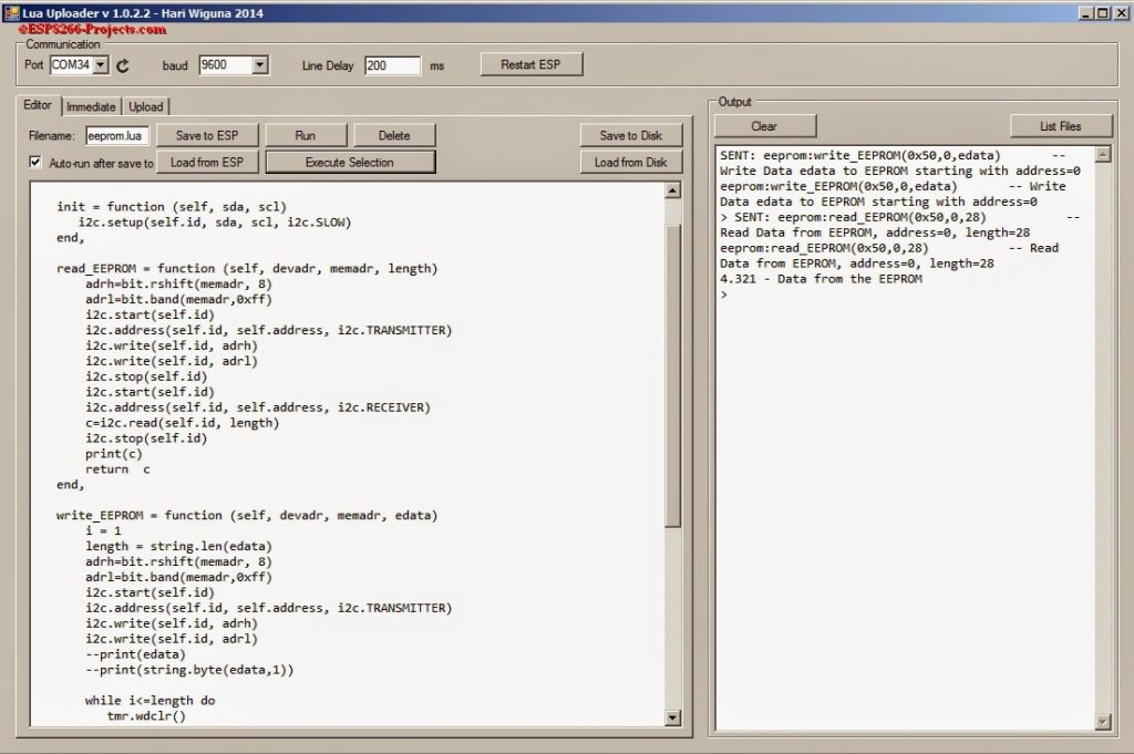
For testing, pack it together and save the code on ESP as ‘eeprom.lua‘, restart ESP and run:
  require('eeprom')                                               -- call for new created AT24C32 Module Driver
  memadr=0x00                                                   -- let's read from begining
  sda, scl = 2, 1                                                    -- I2C pins setup
  edata="4.321 - Data from the EEPROM"        -- Data to write to EEPROM

  eeprom:init(sda,scl)                                   -- Init I2C
  eeprom:write_EEPROM(0x50,0,edata)     -- Write Data edata to EEPROM starting with address=0
  eeprom:read_EEPROM(0x50,0,28)           -- Read Data from EEPROM, address=0, length=28

1 Comment
Aaryadev · February 15, 2019 at 11:07 am
This is Awesome .
I was stuck in writing data to eeprom , was able to read
thanks again .