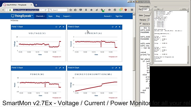
This time we are exploring the Real Time Clock implementation and we will see how easy or complicated is to set & program the onboard RTC Clock.
And the story behind:
For a complete monitoring/ data logging experience, a nice to have feature is a proper RTC clock. Having this in mind, for the new version of the SmartMon I choose to add it on-board for a very simple and easy integration in your related Voltage, Current, Power projects.
The choosen one is the PCF8563 from NXP, a very nice and easy to program CMOS Real-Time Clock (RTC) and Calendar optimized for low power consumption. A programmable clock output, interrupt output and voltage-low detector are also provided. All addresses and data are transferred serially via a two-line bidirectional I2C-bus with a maximum bus speed of 400 kbit/s.
Features:
• Provides year, month, day, weekday, hours, minutes, and seconds based on a
• Century flag
Schematic:
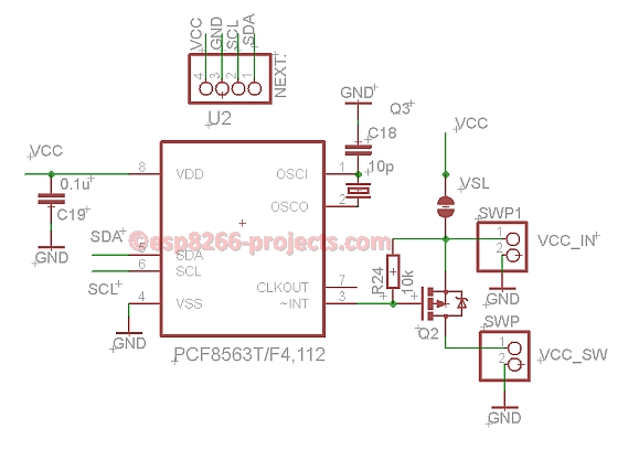 |
| SmartMon v2.7Ex – RTC module schematic |
For more details about the RTC, please see PCF8563 Datasheet and the related PCF8563 RTC clock driver Article
What we will need:
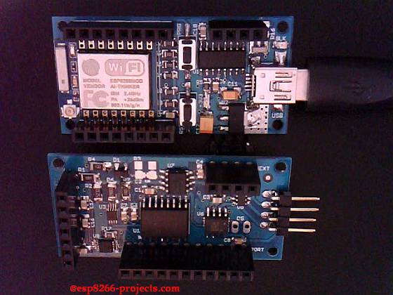
- ESP8266 nEXT EVO Board
- SmartMon v2.7Ex Board
- For programming and uploading the driver and the software we will continue to use the LuaUploader as before.
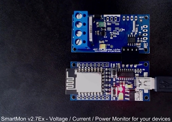
Connection with the ESP8266 nEXT EVO Board is very easy, as Analog Extension Board – AN1 connector is fully compatible with the nEXTBus connector:
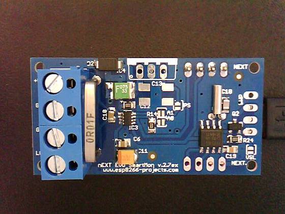 |
| SmartMon v2.7Ex Board |
This time we are talking here about ESP8266/LUA driver but also Arduino implementation will follow.
If you use another ESP8266, or Arduino, ARM, PIC, whatever MCU you use there days for your projects, then just be sure that you are connecting the I2C lines (SDA/SCL) on the allocated pins for your setup.
Driver implementation
As PCF8563 has a I2C compatible compatible interface, driver building it following more or less the same process as before for I2C devices.
For more details about the RTC, please take a deeper look at the PCF8563 Datasheet and the related PCF8563 RTC clock driver Article.
1. Data conversion functions:
1.1 Decimal to BCD:
       function decToBcd(val)
             local d = string.format("%d",tonumber(val / 10))
             local d1 = tonumber(d*10)
             local d2 = val - d1
            return tonumber(d*16+d2)
         end
1.2 BCD to Decimal:
      function bcdToDec(val)
           local hl=bit.rshift(val, 4)
           local hh=bit.band(val,0xf)
          local hr = string.format("%d%d", hl, hh)
          return string.format("%d%d", hl, hh)
     end
        address = 0x51, -- A2, A1, A0 = 0
        id = 0
        init = function (self, sda, scl)
               self.id = 0
              i2c.setup(self.id, sda, scl, i2c.SLOW)
       end
   readTime = function (self)
       wkd = {"Sunday", "Monday", "Tuesday", "Wednesday", "Thursday", "Friday", "Saturday" }
       i2c.start(self.id)
       i2c.address(self.id, self.address, i2c.TRANSMITTER)
       i2c.write(self.id, 0x02)
       i2c.stop(self.id)
       i2c.start(self.id)
       i2c.address(self.id, self.address, i2c.RECEIVER)
       c=i2c.read(self.id, 7)
       i2c.stop(self.id)
       return  bcdToDec(bit.band(string.byte(c,1),0x7f)),
               bcdToDec(bit.band(string.byte(c,2),0x7f)),
               bcdToDec(bit.band(string.byte(c,3),0x3f)),
               bcdToDec(bit.band(string.byte(c,4),0x3f)),
               wkd[tonumber(bcdToDec(bit.band(string.byte(c,5),0x7)))],
               bcdToDec(bit.band(string.byte(c,6),0x1f)),
               bcdToDec(string.byte(c,7))
   end
   setTime = function (self, second, minute, hour, day, date, month, year)
       i2c.start(self.id)
       i2c.address(self.id, self.address, i2c.TRANSMITTER)
       i2c.write(self.id, 0x02)
       i2c.write(self.id, decToBcd(second))
       i2c.write(self.id, decToBcd(minute))
       i2c.write(self.id, decToBcd(hour))
       i2c.write(self.id, decToBcd(day))
       i2c.write(self.id, decToBcd(date))
       i2c.write(self.id, decToBcd(month))
       i2c.write(self.id, decToBcd(year))
       i2c.stop(self.id)
   end
For testing, pack it together and save the code on ESP as ‘pcf8563.lua‘, restart ESP and run:
-- Set Initial Time and Date
 require('pcf8563')                                -- call for new created PCF8563 Module Driver
 sda, scl = 2, 1                                      --  declare your I2C interface PIN's
pcf8563:init(sda, scl)                           -- initialize I2C Bus
  pcf8563:setTime(0,34,13,12,4,3,15)   -- setTime(s,min,hour,day,weekday,month, year)
 -- get Time and Date
 require('pcf8563')
 sda, scl = 2, 1
 pcf8563:init(sda, scl)

s, m, h, d, dt, mn, y = pcf8563:readTime()        --ReadTime function call
=string.format("%s - %s/%s/20%s",dt, d, mn, y)
=string.format(" %s:%s:%s", h, m, s)
Next Article in series can be found here Part 3: INA219 Driver example and software implementation
 SmartMon series boards, software and articles by ESP8266-Projects.com are licensed under a Creative Commons Attribution-NonCommercial 4.0 International License.