————————————————— DISCLAIMER ————————————————–
WARNING!! You will play with LIVE MAINS!! Deadly zone!!
If you don’t have any experience and are not qualified for working with MAINS power I will not encourage you to play arround!. The author take no responsibility for any injury or death resulting, directly or indirectly, from your inability to appreciate the hazards of household mains voltages.
The circuit diagrams are as accurately as possible, but are offered with no guarantees whatsoever.
There is no guarantee that this design meets any Rules which may be in force in your country so please check before your local rules/regulations.
———————————————————————————————————————————
As I was asked by many of you , I will repost the MPDMv4 AC MAINS Dimmer Arduino IDE Driver example below:
/*
 Dimmer

 Demonstrates the sending data from the computer to the Arduino board,
 in this case to control the brightness of MPDMv4 AC MAINS Dimmer.
 The data is sent in individual VCNT, each of which ranges from 0 to around 890. Arduino
 reads these bytes and uses them to set the VCNT brightness command .

 The circuit:
 MPDMv4 Board attached from digital pin 5 to ground.

 created 2006
 by David A. Mellis
 modified 30 Aug 2011
 by Tom Igoe and Scott Fitzgerald
 modified 14 Apr 2016
 by TJ for esp8266-projects.com AC MAINS Power Dimmer MPDMv4 Driver
 This example code is in the public domain.

 */

const int vcntPin = 5; // the ESP8266 Board GPIO PIN that the MPDMv4 VCNT pin is attached to

void setup()
{
 // initialize the serial communication:
 Serial.begin(9600);
 // initialize the VCNTPin as an output:
 pinMode(vcntPin, OUTPUT);
 // set default brightness value
 analogWrite(vcntPin, 200);
}

void loop() {
 int brightness;

// check if data has been sent from the computer:
 if (Serial.available() > 4) {
 brightness = Serial.parseInt();
 Serial.print("Command received : ");
 Serial.println(brightness);
 // set the brightness of the LED:
 analogWrite(vcntPin, brightness);
 }
}
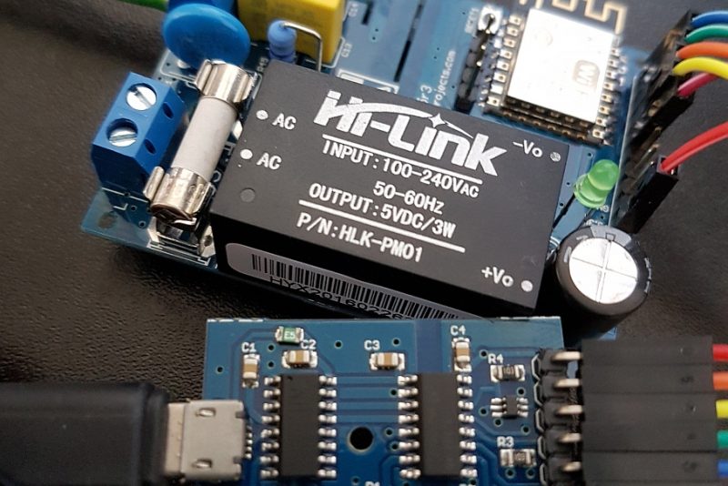
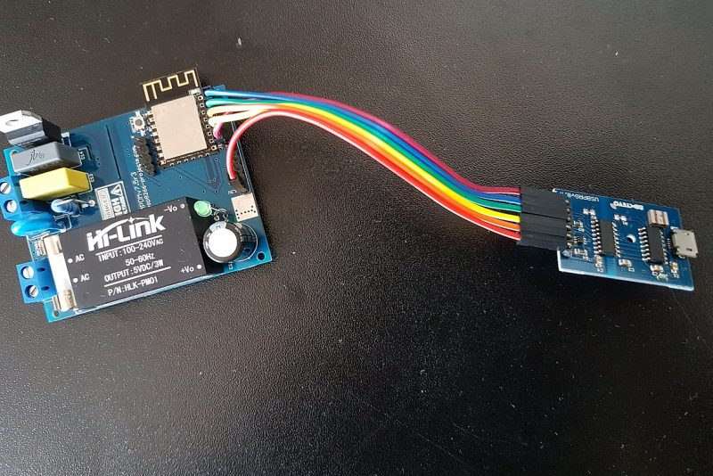
As you can see above, the only thing that you need is to provide a proper voltage control on the MPDMv4 VCNT pin, all the other stuff, phase detection, ZCD, etc, are done by the MPDMv4 module itself.
It is properly working with ESP8266, ESP32, Arduino UNO, Mega, etc.
Happy breadboarding,
TJ.
For any new orders/requests please feel free to use as usual: tech at esp8266-projects.com.
MPDMv4 Boards are also available on Tindie: AC MAINS Dimmer – MPDMv4
———————————————————————————————————————————
![]() MPDMv4 by ESP8266-Projects.com is licensed under a Creative Commons Attribution-NonCommercial 4.0 International License.
MPDMv4 by ESP8266-Projects.com is licensed under a Creative Commons Attribution-NonCommercial 4.0 International License.
—————————————————————————————————————————