What we will need:
- CBDB Board
- USB adapter (take a look on Part 1 for details how to connect them together)
- DS3231 Module – you can buy them at a very good price HERE, 1.62USD/pcs, a very good deal!!
For programming and uploading the driver and the software we will continue to use the LuaUploader as before.
If you remember my article about PCF8563 Real Time Clock this one was a looong avaited MailBox hit. Actually I didn’t expect it to show anymore after so much time but miracles happening sometime :)The DS3231 is a extremely accurate I2C real-time clock (RTC) with an integrated temperature-compensated crystal oscillator (TCXO) and crystal.
The device incorporates a battery input, and maintains accurate timekeeping when main power to the device is interrupted. The integration of the crystal resonator enhances the long-term accuracy of the device as well as reduces the piece-part count in a manufacturing line.
The RTC maintains seconds, minutes, hours, day, date,month, and year information. The date at the end of the month is automatically adjusted for months with fewer than 31 days, including corrections for leap year. The clock operates in either the 24-hour or 12-hour format with an AM/PM indicator.
Two programmable time-of-day alarms and a programmable square-wave output are provided. Address and data are transferred serially through an I2C bidirectional bus.
A precision temperature-compensated voltage reference and comparator circuit monitors the status of VCC to detect power failures, to provide a reset output, and to automatically switch to the backup supply when necessary. Additionally, the RST pin is monitored as a pushbutton input for generating a μP reset.
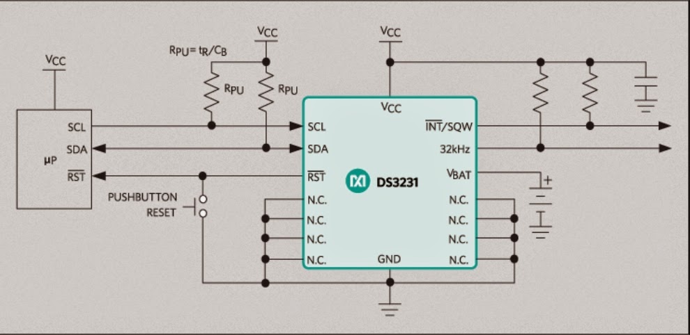 |
| DS3231 Typical Operating Circuit |
FEATURES :
- Highly Accurate RTC Completely Manages All Timekeeping Functions
• Real-Time Clock Counts Seconds, Minutes, Hours, Date of the Month, Month, Day of
the Week, and Year, with Leap-Year Compensation Valid Up to 2100
• Accuracy ±2ppm from 0°C to +40°C
• Accuracy ±3.5ppm from -40°C to +85°C
• Digital Temp Sensor Output: ±3°C Accuracy
• Register for Aging Trim
• Active-Low RST Output/Pushbutton Reset Debounce Input
• Two Time-of-Day Alarms
• Programmable Square-Wave Output Signal
- Simple Serial Interface Connects to Most Microcontrollers
• Fast (400kHz) I2C Interface
- Battery-Backup Input for Continuous Timekeeping
• Low Power Operation Extends Battery-Backup Run Time
• 3.3V Operation
- Operating Temperature Ranges: Commercial (0°C to +70°C) and Industrial (-40°C to +85°C)
- Underwriters Laboratories® (UL) Recognized
For more details, please see DS3231 Datasheet
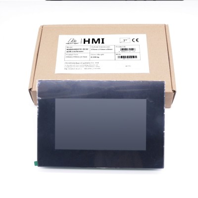
DS3231 Module
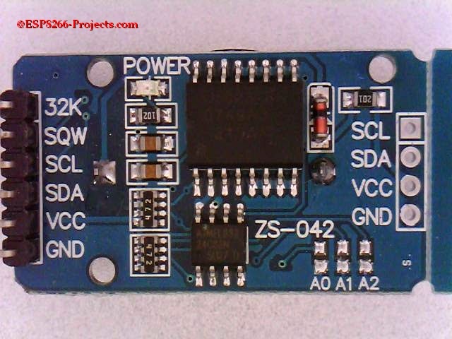 |
| Top |
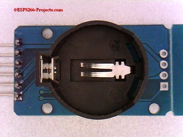 |
| Bottom |
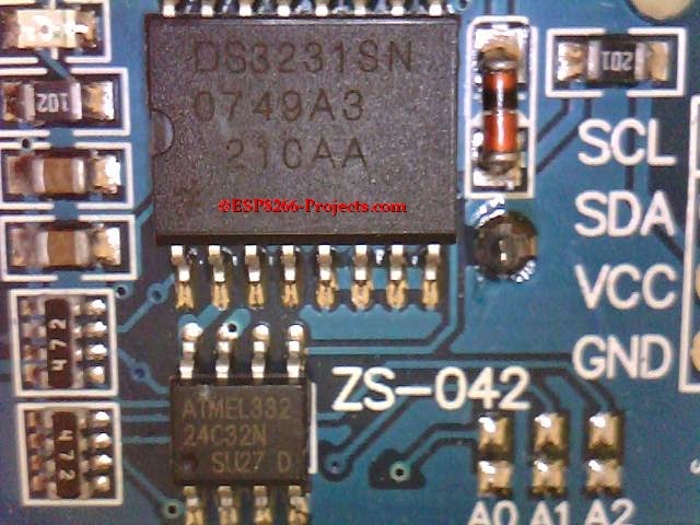 |
| Close-up |
As you can see from the pictures above, a nice compact module, with backup battery holder on the back (CR2032). Also you can find on the same module sharing the I2C bus a 24C32N EEPROM ( 32k – 4096 x 8) , totally independent from the RTC circuit. A nice addon for a possible WIFI Datalogger system, what do you think about? 🙂
32k might sound a small amount of data storage but depending on your application requests might be more than enough for collecting 6 moths or a year data, even more. As I know already from your requests that this subject is of big interest, we will elaborate more about this one in the next article, for now let’s go back to our fancy RTC 🙂
Clock and Calendar – Theory of operation
The time and calendar information is obtained by reading the appropriate register bytes. The time and calendar data are set or initialized by writing the appropriate register bytes. The contents of the time and calendar registers are in the binary-coded decimal (BCD) format.
The DS3231 can be run in either 12-hour or 24-hour mode. Bit 6 of the hours register is defined as the 12- or 24-hour mode select bit. When high, the 12-hour mode is selected. In the 12-hour mode, bit 5 is the AM/PM bit with logic-high being PM. In the 24-hour mode, bit 5 is the 20-hour bit (20–23 hours).
The century bit (bit 7 of the month register) is toggled when the years register overflows from 99 to 00.
The day-of-week register increments at midnight. Values that correspond to the day of week are user-defined but must be sequential (i.e., if 1 equals Sunday, then 2 equals Monday, and so on). Illogical time and date entries result in undefined operation.
When reading or writing the time and date registers, secondary (user) buffers are used to prevent errors when the internal registers update. When reading the time and date registers, the user buffers are synchronized to the internal registers on any START and when the register pointer rolls over to zero. The time information is read from these secondary registers, while the clock continues to run. This eliminates the need to reread the registers in case the main registers update during a read.
The countdown chain is reset whenever the seconds register is written. Write transfers occur on the acknowledge from the DS3231. Once the countdown chain is reset, to avoid rollover issues the remaining time and date registers must be written within 1 second.
The 1Hz square-wave output, if enabled, transitions high 500ms after the seconds data transfer, provided the oscillator is already running.
Driver implementation
As DS3231 has a I2C compatible compatible interface, driver building it following more or less the same process as before for I2C devices.
1. Data conversion functions:
1.1 Decimal to BCD:
         function decToBcd(val)
             local d = string.format("%d",tonumber(val / 10))
             local d1 = tonumber(d*10)
             local d2 = val - d1
            return tonumber(d*16+d2)
         end
       function bcdToDec(val)
           local hl=bit.rshift(val, 4)
           local hh=bit.band(val,0xf)
          local hr = string.format("%d%d", hl, hh)
          return string.format("%d%d", hl, hh)
     end
         address = 0x51, -- A2, A1, A0 = 0
        id = 0
        init = function (self, sda, scl)
               self.id = 0
              i2c.setup(self.id, sda, scl, i2c.SLOW)
       end
       readTime = function (self)
       wkd = {"Sunday", "Monday", "Tuesday", "Wednesday", "Thursday", "Friday", "Saturday" }
       i2c.start(self.id)
       i2c.address(self.id, self.address, i2c.TRANSMITTER)
       i2c.write(self.id, 0x00)
       i2c.stop(self.id)
       i2c.start(self.id)
       i2c.address(self.id, self.address, i2c.RECEIVER)
       c=i2c.read(self.id, 7)
       i2c.stop(self.id)
       return  bcdToDec(string.byte(c,1)),
               bcdToDec(string.byte(c,2)),
               bcdToDec(string.byte(c,3)),
               wkd[tonumber(bcdToDec(string.byte(c,4)))],
               bcdToDec(string.byte(c,5)),
               bcdToDec(string.byte(c,6)),
               bcdToDec(string.byte(c,7))
   end
   setTime = function (self, second, minute, hour, day, date, month, year)
       i2c.start(self.id)
       i2c.address(self.id, self.address, i2c.TRANSMITTER)
       i2c.write(self.id, 0x00)
       i2c.write(self.id, decToBcd(second))
       i2c.write(self.id, decToBcd(minute))
       i2c.write(self.id, decToBcd(hour))
       i2c.write(self.id, decToBcd(day))
       i2c.write(self.id, decToBcd(date))
       i2c.write(self.id, decToBcd(month))
       i2c.write(self.id, decToBcd(year))
       i2c.stop(self.id)
   end
-- Set Initial Time and Date
 require('ds3231')                                -- call for new created DS3231 Module Driver
 sda, scl = 2, 1                                      --  declare your I2C interface PIN's
 ds3231:init(sda, scl)                           -- initialize I2C Bus
  ds3231:setTime(5,08,12,3,6,04,15)   -- setTime(s,min,hour,weekday,day,month, year)
 -- get Time and Date
 require('ds3231')
 sda, scl = 2, 1
 ds3231:init(sda, scl)

s, m, h, d, dt, mn, y = ds3231:readTime()
=string.format("%s - %s/%s/20%s",d, dt, mn, y)
=string.format(" %s:%s:%s", h, m, s)
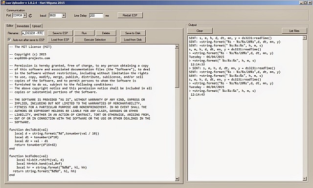 |
| First run test |
5. Read Time & Date – Print on LCD
  require('st7032i')
   sda, scl = 2, 1
   st7032i:init_i2c(sda, scl)
   st7032i:init_LCD()

   Time_LCD = function()
       s, m, h, d, dt, mn, y = ds3231:readTime()
       date = string.format("%s",dt).."/"..string.format("%s",mn).."/"..string.format("20%s",y)
       st7032i:lcd_print(3,1,date)
       time = string.format("%s",h)..":"..string.format("%s",m)..":"..string.format("%s",s)
       st7032i:lcd_print(4,2,time)
   end

   tmr.alarm(0, 1000, 1, function() Time_LCD() end)  -- set call Time_LCD function Timer