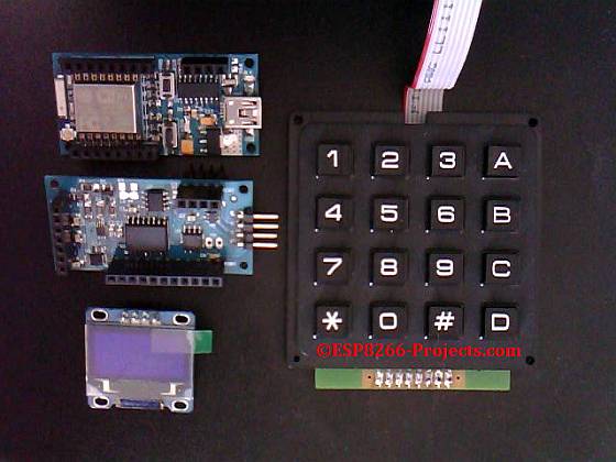
Part 3 of the ESP8266 nEXT Evolution Board Series
Analog Extension Board – AN1
————————————————————————————————————————–
For any new CBDB orders/requests please feel free to use as usual:
tech at esp8266-projects.com.
CBDB nEXT Evo bare PCB has also been made available directly at Dirty PCBs, our preferred PCB House for experimenting (**):
http://dirtypcbs.com/view.php?share=9699&accesskey=91d782fd4a10943fd36ecc371c7ff2cd
(**) – Actually you have there 2 Boards for the price of one, a CBDB nEXT Evo together with a secondary nEXT Extesion Board that brings you a 18Bit ADC (autoscale 0-40V input!), 4x12Bit DAC, Precison Temperature measurement, 8bit I/O port, etc.
————————————————————————————————————————-
 |
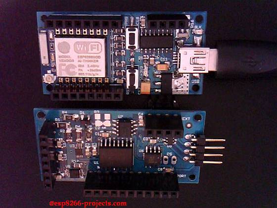
| CBDB nEXT A1 Extension Board – TOP |
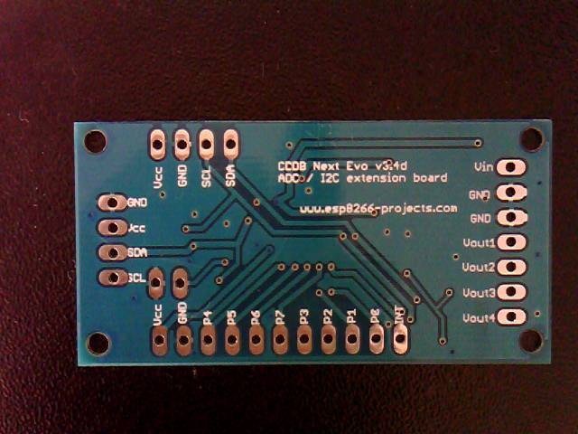 |
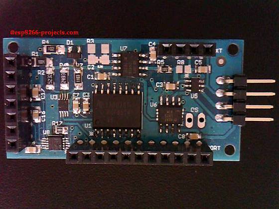
| CBDB nEXT A1 Extension Board -Bottom |
Basic default functions of the CBDB nEXT A1 Extension Board:
INPUT :
- 0-40V Autorange Analog frontend
- 18 Bit ADC
OUTPUT :
- 4×12 BIT DAC
TEMPERATURE :
- I2C Temperature sensor, standard or high precision options
I/O :
- 8 Bit I/O Port
Analog frontend input
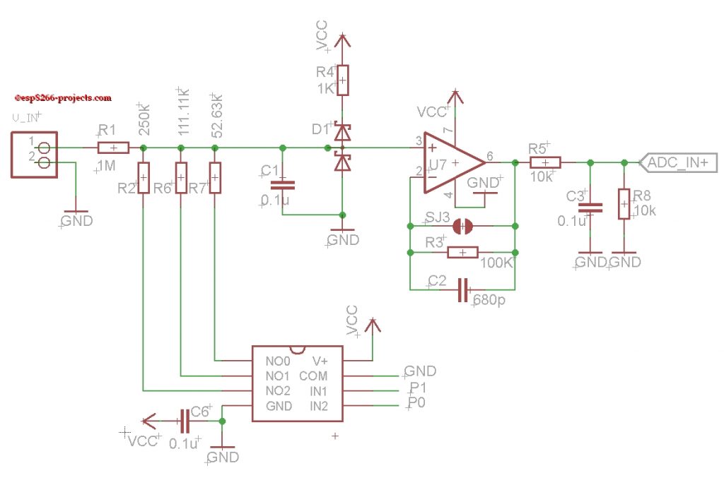
With the default resistor divider values you can have 4 different autoranging scales as below:
- 0 – 20V
- 0 – 10V
- 0 – 20 V
- 0 – 40 V
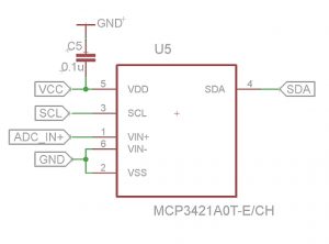
Analog to digital conversion
For this board, the choosen ADC is the MCP3421 from Microchip.
The MCP3421 is a single channel, low-noise, high accuracy delta-sigma A/D converter with differential inputs and up to 18 bits of resolution in a small SOT-23-6 package. The on-board precision 2.048V reference voltage enables an input range of ±2.048V differentially.
The device uses a two-wire I2C compatible serial interface and operates from a single power supply ranging from 2.7V to 5.5V.
This device has an onboard programmable gain amplifier (PGA). User can select the PGA gain of x1, x2, x4, or x8 before the analog-to-digital conversion takes place. This allows the MCP3421 device to convert a smaller input signal with high resolution.
For more details about MCP3421 please read the related article: MCP3421 – 18bit I2C ADC – Driver
You will find there driver details and detailed tests regarding MCP3421 ADC.
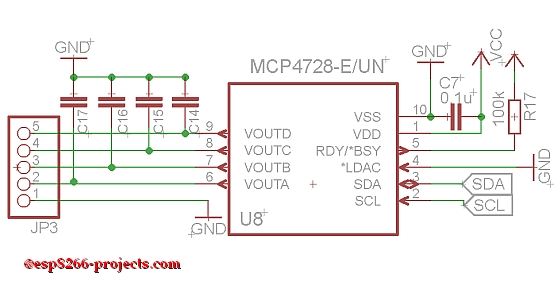
Digital to Analog conversion
For the 4 DAC channels we will use the MCP4728 12 Bit Quad Digital-to-Analog Converter with EEPROM Memory.
MAIN Features:
• 12-Bit Voltage Output DAC with Four Buffered Outputs
• On-Board Nonvolatile Memory (EEPROM) for DAC Codes and I2C™ Address Bits
• Internal or External Voltage Reference Selection
• Output Voltage Range:
– Using Internal VREF (2.048V):
0.000V to 2.048V with Gain Setting = 1
0.000V to 4.096V with Gain Setting = 2
– Using External VREF (VDD): 0.000V to VDD
• ±0.2 Least Significant Bit (LSB) Differential Nonlinearity (DNL) (typical)
• Fast Settling Time: 6 μs (typical)
• Normal or Power-Down Mode
• Low Power Consumption
• Single-Supply Operation: 2.7V to 5.5V
• I2C Interface:
– Address bits: User Programmable to EEPROM
– Standard (100 kbps), Fast (400 kbps) and High Speed (HS) Mode (3.4 Mbps)
• 10-Lead MSOP Package
• Extended Temperature Range: -40°C to +125°C
Actually, from the DAC point of view you can see MCP4728 as the bigger brother of the MCP4726, Single 12 Bit DAC used before in examples below:
Temperature
For the remperature reading you can use the standard LM75 sensor OR if you want more precision the MCP9808 one.
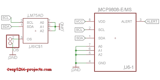
Drivers and basic examples for both, below:
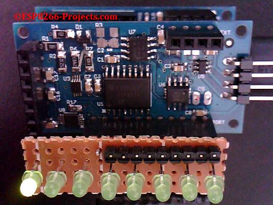
I/O Expander Port
The I/O expander port is based on the PCF8574, a 8-bit remote I/O port for the I2C-bus.
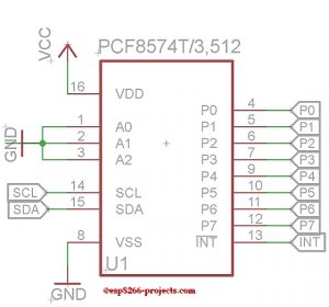
The device consists of an 8-bit quasi-bidirectional port and an I2C-bus interface. The PCF8574 has a low current consumption and includes latched outputs with high current drive capability for directly driving LEDs.
Another interting feature is the interrupt line (INT) which can be connected to the interrupt logic of the microcontroller. By sending an interrupt signal on this line, the remote I/O can inform the microcontroller if there is incoming data on its ports without having to communicate via the I2C-bus. This means that the PCF8574 can remain a simple slave device, even for data input, keyboard scanning, etc.
That’s all for now, next times we will continue testing and exploring step-by-step each function of the ESP8266 nEXT Evo Extension Board